528 Pin configuration and power supply
imc CANSAS Users Manual - Doc. Version 1.9 - 05.12.2014© 2014 imc Meßsysteme GmbH
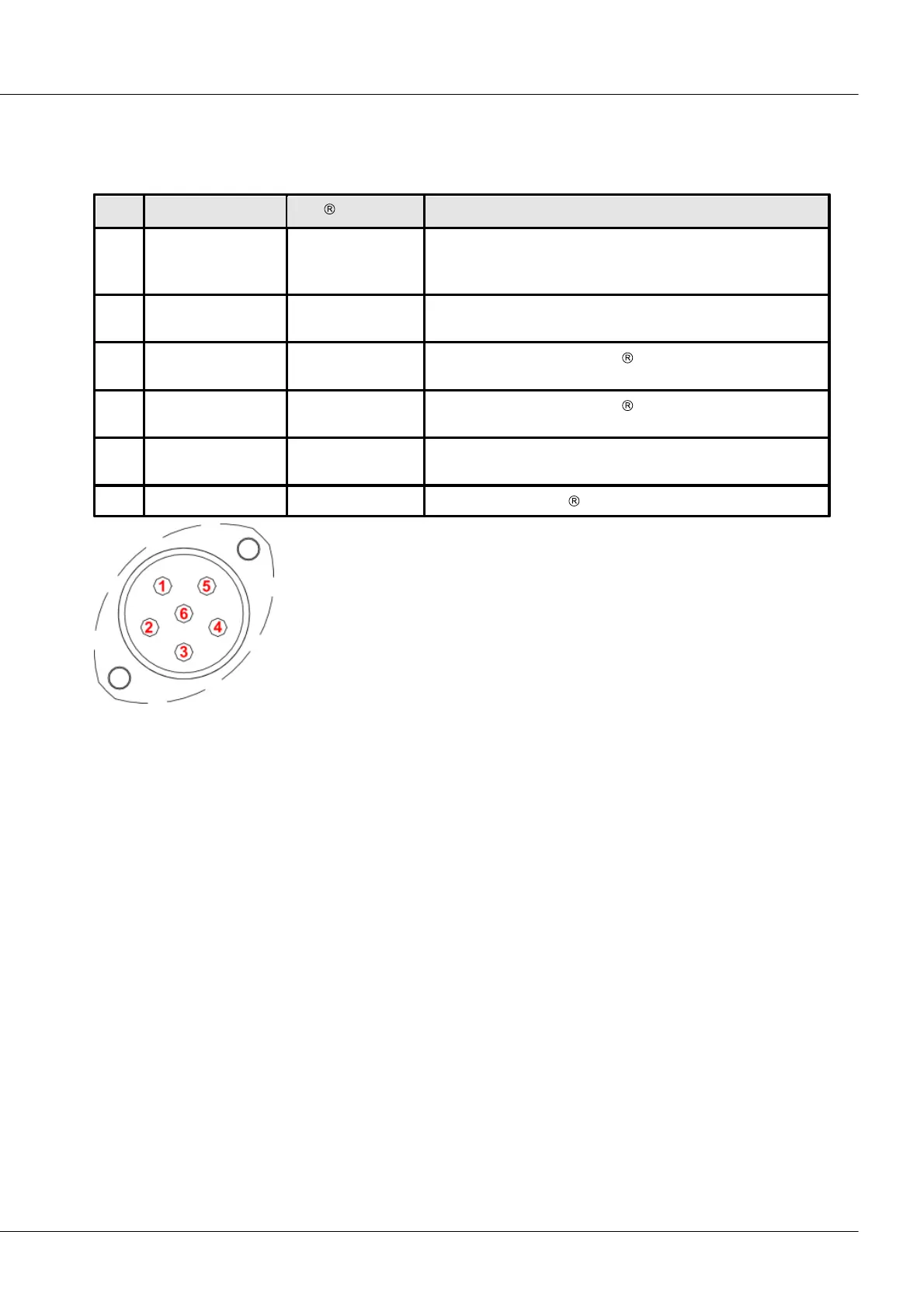
8.1.3.1 CAN-Bus pin configuration and contact wiring
8.1.3.1.1 Autosport (µ-CANSAS-XX-AS)
Pin configuration and wiring for the CAN-bus
imc CANSAS-specific:
+ imc CANSAS supply +9…+50 V. The module is supplied via
the pins +CAN_SUPPLY and –SUPPLY.
imc CANSAS-specific: - imc CANSAS power supply (minus
contact: 0V).
Connected as specified by CiA
Connected as specified by CiA
imc CANSAS-specific: imc CANSAS Reset. Must be jumpered
with CAN_GND for a reset.
Connected as per CiA . CAN-bus reference ground
6-pin Autosport terminal
type AS208-35
Pins 3 and 4 are absolutely necessary for transmission on the CAN-Bus, as
well as the CAN-Bus ground. According to specifications, the differential
signals require a reference, for which reason a CAN-Bus ground connection
is also needed. For this purpose pin 6 can be used. There are situations
where the CAN ground is not necessary: for example, on board vehicles, if
instead of a line to pin 6 it is possible to make contact with anywhere on the
chassis. In that case, the chassis is a substitute for the line to pin 6.
Other lines can be used for the purpose if necessary, for instance the
power supply line.
Note when using Autosport plugs and cables, that there is a limit on the maximum current through the
Autosport-plug. The current should not exceed approx. 5A. An accordingly high power supply voltage for
the modules may need to be used.
Check the cross-section of the cables.