332 Properties of the Modules
imc CANSAS Users Manual - Doc. Version 1.9 - 05.12.2014© 2014 imc Meßsysteme GmbH
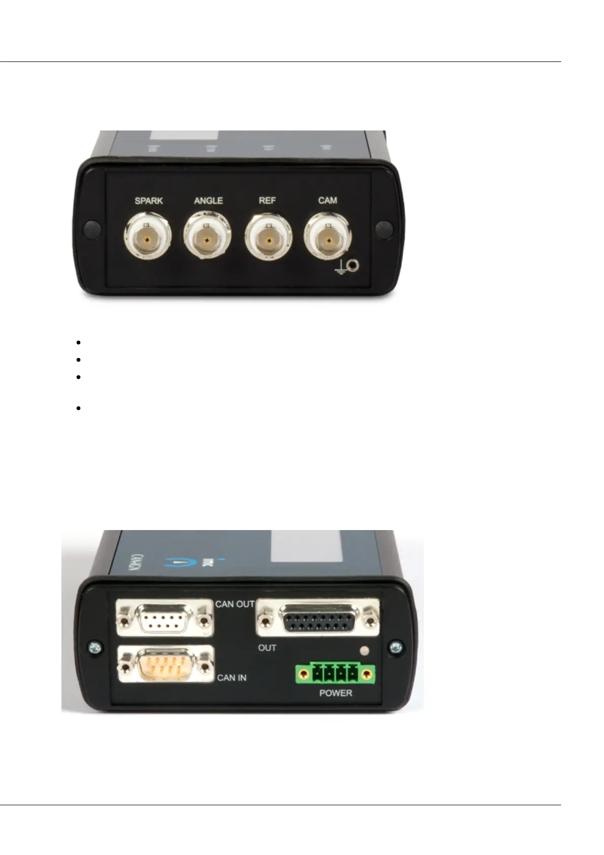
6.11.6 IGN terminal
6.11.6.1 Inputs (BNC)
4 isolated BNC sockets for 4 isolated input channels:
SPARK: connector for the ignition signal
ANGLE: connector for the crankshaft sensor
REF: If an incremental counter is used as the crankshaft sensor, the counter's zero-output is
connected here.
CAM: The camshaft sensor is only connected to this input in the case of Monitoring of Selected
Cylinders. This returns one pulse per revolution of the camshaft.
Uniform conditioning is provided for all 3 signals: voltage isolation, bandwidth approx. 600 kHz, 40 V
input range.
6.11.6.2 Output (DSUB-15)
This terminal provides the analog and digital outputs and auxiliary power supply. The outputs and power
supply are not isolated against the module's power supply.
CANSS-IGN: CAN-connector and analog/digital outputs