446 Properties of the Modules
imc CANSAS Users Manual - Doc. Version 1.9 - 05.12.2014© 2014 imc Meßsysteme GmbH
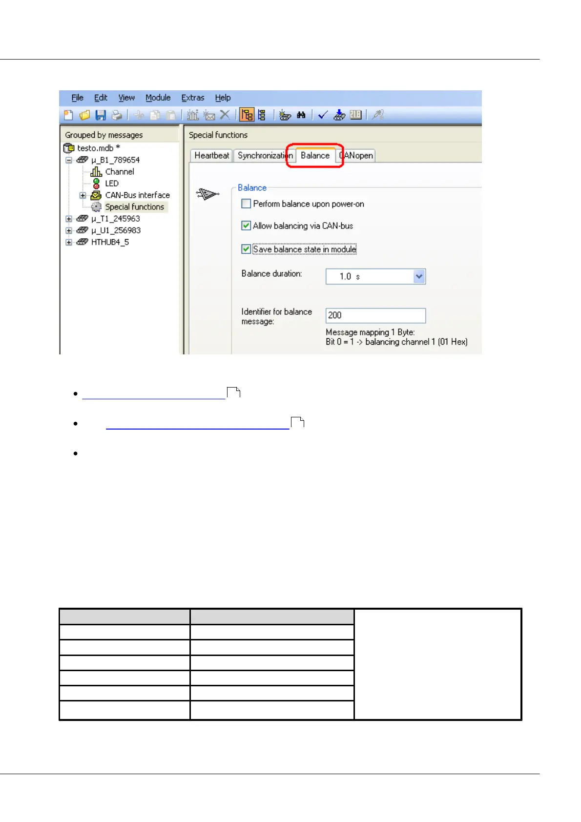
6.23.4 Bridge balancing
µ-CANSAS-B1: Balancing dialog
With imc µ-CANSAS-B1, there are a variety of ways to perform balancing:
Bridge balancing upon power-up automatically balances out the zero offset as soon as the
module is activated.
With Perform bridge balancing via the CAN-bus , a CAN-Bus message initiates the balancing
process.
The balancing procedure is performed in the measurement window.
Save balance state in module:
This optional setting ensures that the balancing values are not lost once the device is deactivated.
Balance duration:
Data acquisition for determining the averaged balancing value. If the input signal fluctuates somewhat
around the rest state, a longer duration can cancel out these fluctuations.
Identifier:
A message to perform balancing must bear the identifier set here.
Any initial unbalance of the measurement bridge, for instance due to mechanical pre-stressing of the
strain gauge in its rest state, must be zero-balanced. If the initial unbalance is too large to be
compensated by the device, a larger input range must be set.
Bridge balancing*(VB = 5V) [mV/V]
*The bridge balancing is the difference
between the input range set and the
possible input range. For instance, if the
actual range for a setting of 200 mV/V is
235 mV/V and the one for the 100 mV/V
setting is 118 mV/V, then the resulting
possible initial unbalance is 35 mV/V in
the 200 mV/V input range and 18 mV/V
in the 100 mV/V input range.
447
447