DCB8: bridge, strain gauges 293
imc CANSAS Users Manual - Doc. Version 1.9 - 05.12.2014© 2014 imc Meßsysteme GmbH
6.7.1 Bridge measurement
The measurement channels have an adjustable DC voltage source which supplies the measurement of
bridges such as strain gauges. The supply voltage for a group of eight inputs is set in common. The bridge
supply is asymmetric, e.g., for a bridge voltage setting of VB=5 V, Pin +VB is at +VB=5 V and Pin -VB at
-VB=0 V. The terminal –VB is simultaneously the device's ground reference.
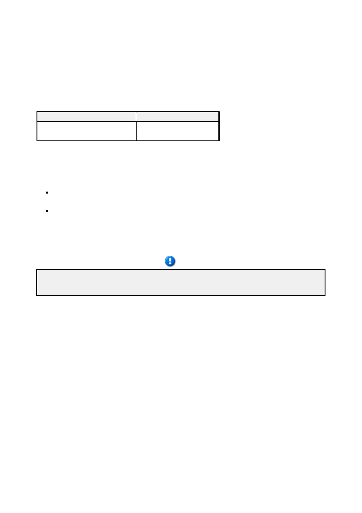
Per default 5 V and 10 V can be selected as bridge supply. Depending on the supply set, the following
input ranges are available:
Fundamentally, the following holds: For equal physical modulation of the sensor, the higher the selected
bridge supply is, the higher are the absolute voltage signals the sensor emits and thus the
measurement's signal-to-noise ratio and drift quality. The limits for this are set by the maximum
available current from the source and by the dissipation in the sensor (temperature drift!) and in the
device (power consumption!)
For typical measurements with strain gauges, the ranges 5 mV/V to 1 mV/V are particularly
relevant.
There is a maximum voltage which the potentiometer sensors are able to return, in other words
max. 1 V/V; a typical range is then 1000 mV/V.
Bridge measurement is set by selecting as measurement mode either Bridge: Sensor or Bridge: Strain
gauge in the operating software. The bridge circuit itself is then specified under the tab Bridge circuit,
where quarter bridge, half bridge and full bridge are the available choices.
We recommend to angle a maximum range on the not used voltage measurement. An open entry in
half- or quarter bridge mode can annoy the neighbor channels if this is also in half- or quarter bridge
mode.