256 Properties of the Modules
imc CANSAS Users Manual - Doc. Version 1.9 - 05.12.2014© 2014 imc Meßsysteme GmbH
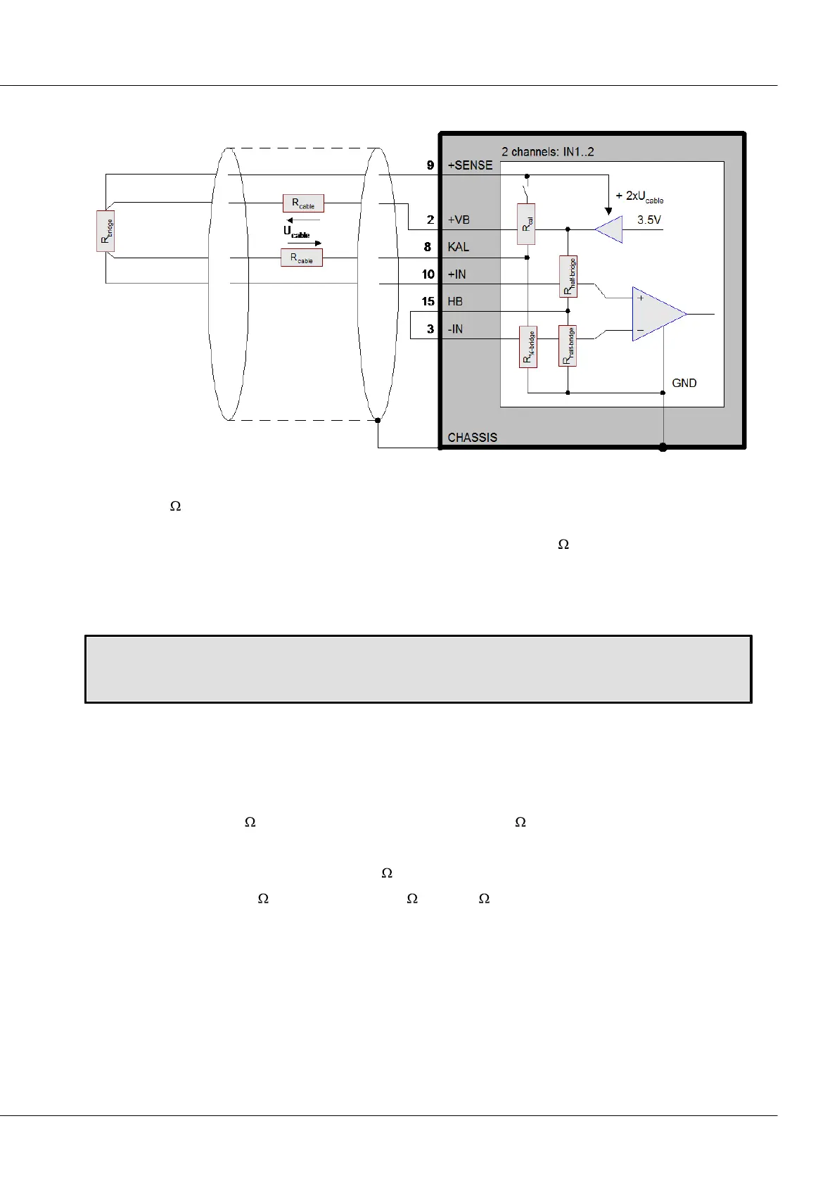
6.1.4 Quarter bridge
Bridge2: block diagram quarter bridge
If the sensor consists of only one resistor, it's possible to complete the bridge with three additional
resistors. 120 can be selected for the external resistor with which to construct a half bridge. This
resistor is switched on electronically. In order to select the resistance for the quarter bridge, “Sensor”
must be selected as the measurement target and “Quarter bridge with 120 ” must be selected as the
bridge configuration.
Important note: As with the half bridge, a jumper must be connected between “HB1” or “HB2” and the
corresponding input pin in order to activate the necessary half bridge completion. This half bridge
completion in turn is also internal.
Setting the quarter bridge:
Channel0x -> Index card “Inputs” -> Measurement target combo box: “Sensor”
Channel0x -> Index card “Bridge circuit” -> Configuration combo box: “Quarter bridge”
Quarter-bridge configuration, using four (symmetric) cables, enables measurement of an external ¼-
bridge branch. If a gain error is considered an acceptable trade-off, it is possible to go without the
"+SENSE" line, but not without separate lines for "KAL" and "+IN": Otherwise, an unacceptable offset-
drift would result, since the temperature-dependent cable resistance is connected in series with to
quarter bridge directly. If we assume a cable length (one-way) of 1 m, we obtain:
Cu-cable 0,14mm², 130m /m, cable length l =1m cable Rk = 130m
Temperature coefficient Cu:
Drift Rk
Equivalent bridge drift (120 bridge)
Example, temperature change dT = 20K
4000ppm / K
0,52m / K
½ * 0,52m / (K *120 ) = 2,2µV/V / K
44µV/V (dT =20K)
For the optional adjustable calibration resistance, the following applies for all three configurations:
Connection to a separate line avoids an error of the shunt calibration magnitude of Rb / R_kal caused by
the cable resistance to a. In quarter bridge configuration, this is inevitable, since the calibration resistor is
already connected to the quarter bridge internally and even shares the pin "CAL".
Going without a separate line for "+SENSE" and direct jumpering of "+SENSE" and "+VB" at the
connection terminal causes a gain error of Rk/Rb in all configurations.