Integrating the imc CANSAS software with imc DEVICES 37
imc CANSAS Users Manual - Doc. Version 1.9 - 05.12.2014© 2014 imc Meßsysteme GmbH
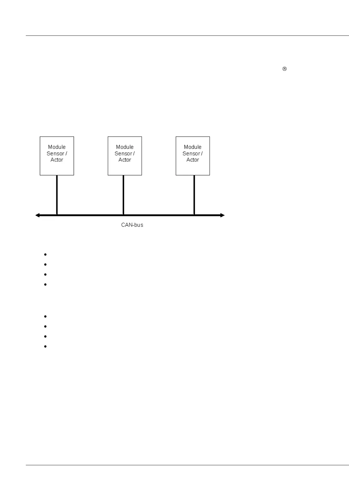
2.6 CAN-Bus description
The CAN-Bus (CAN = Controller Area Network) is a serial connection of all modules, with terminators at
the line's ends. imc CANSAS is designed to be operated on a CAN-Bus which complies with CiA
standards (CiA Draft Standard 102 Version 2.0, CAN Physical Layer for Industrial Applications).
Multiple sensors and devices are connected onto the CAN-Bus and send data (at a fixed rate) via the bus.
Each device (or sensor) transmits its data to the bus together with an identifier. The identifier provides an
unambiguous indication of the source and sense of the data. An identifier is a packet of data up to 8
Bytes in length.
Each CAN-module is referred to as a node. A node can also be a sensor, control device, or a imc CANSAS-
module's primary connection.
2.6.1 References to standards and literature
CiA® Draft Standard 102 Version 2.0: CAN Physical Layer
CAN Controller Area Network by Wolfhard Lawrenz, Hüthig Verlage, 1994 Heidelberg
ISO / DIS 11898 (ISO 11519-2) for bus drivers
ISO / OSI reference model
2.6.2 Bus-activation
CAN Transceiver as per ISO / DIS 11898
galvanic isolation
Baud rate set using software
Standard-Identifier for CAN-Bus: 11Bit Identifier (0..2047) or 29Bit extended Identifier.