Function Reference 179
imc CANSAS Users Manual - Doc. Version 1.9 - 05.12.2014© 2014 imc Meßsysteme GmbH
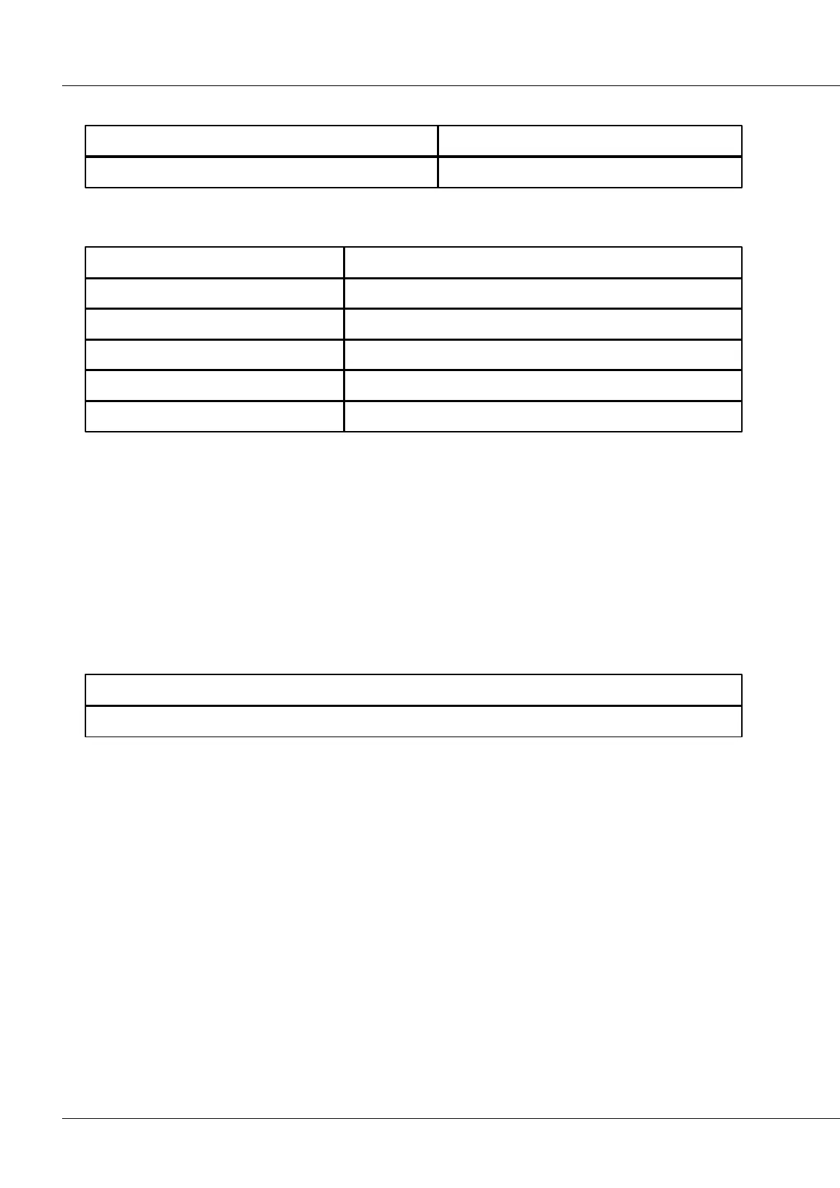
Data types:
4.10.64 Triangle (only for DAC8 modules)
Data rate of result channel.
No. of clock cycles with positive slopes
How many signal clock cycles are to have positive slopes?
No. of clock cycles with negative slopes
How many signal clock cycles are to have negative slopes?
The maximum signal amplitude in V
Description: Outputs a triangle function at the voltage output. The specified number of clock cycles for
the positive slope determines how many cycle durations the signal needs to reach the specified
maximum amplitude. The specified number of clock cycles for the negative slope determines how many
cycle durations the signal needs to return from the maximum amplitude back to 0 V.
Resulting frequency = 1 / ((No. of cycles with pos. slope + No. of cycles with neg. slope) * clock pulse)
The result clock pulse should be as close to 0.1ms as possible. The higher the pulse rate is, the more
accurately the ideal signal shape is approximated. The resulting triangular signal period must not be too
short. If the signal is analog output, the staircase-shaped signal generated by the DA-converter is slightly
filtered (at 5kHz). The resulting curve shape resembles a triangle at high frequencies and a long signal
period.
Data types: