390 Properties of the Modules
imc CANSAS Users Manual - Doc. Version 1.9 - 05.12.2014© 2014 imc Meßsysteme GmbH
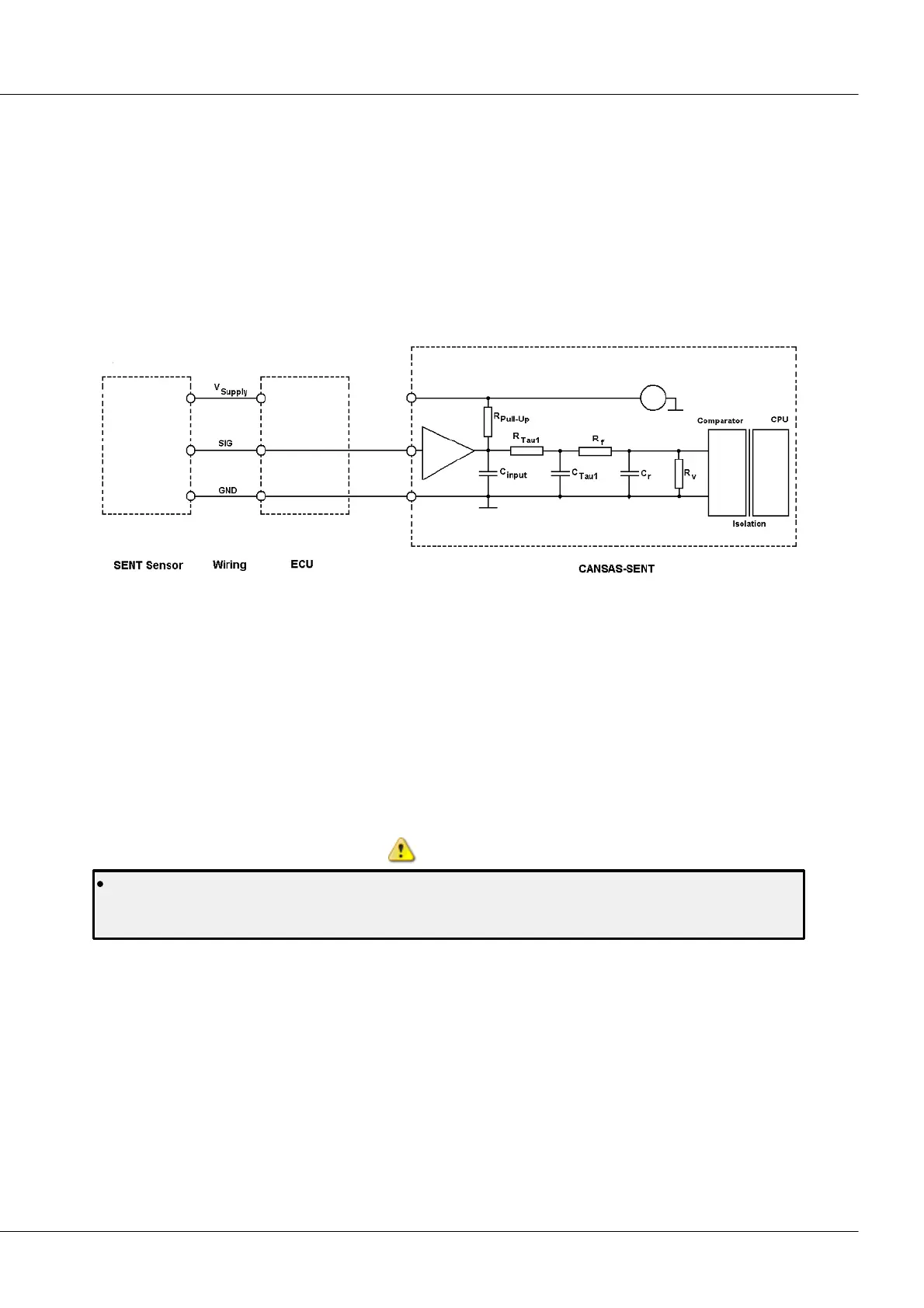
6.19.1.2 Interference-free signal tapping
A SENT sensor to be used for measuring with imc CANSAS-SENT may already be installed and wired up. In
that case, the SENT sensor is connected with another device which has the input circuitry conformant to
SAE J2716 and which already supplies the SENT sensor. On board a vehicle, this other device is typically a
control unit, such as the Engine Control Unit (ECU). This setup is the basis of the following examples.
If the sensor is already being operated with the ECU, then according to SAE J2716, it is not permitted to
simply connect an additional SENT input circuit in parallel. Otherwise, there would be 2 parallel pull-up
resistors and the resulting input impedance may be too low. Therefore, in interference-free tapping, the
signal is tapped at high impedance, which avoids affecting the signal. This makes it possible to use the
CANSAS-SENT module even with a SENT sensor used for closed-loop engine control purposes.
In this arrangement, the SENT sensor is connected with an ECU for closed-loop control purposes, and is
supplied with power by the ECU. Additionally, the imc CANSAS-SENT module is connected. Since the
sensor is already supplied with power from the ECU, it may not also be connected with any additional
voltage source. The sensor’s input V
Supply
is not connected with the imc CANSAS module. The CANSAS
module’s output V
Supply
remains open and unused. The ground line (GND) as well as the signal line (SIG)
must be connected between the sensor and imc CANSAS module. The CANSAS input circuit is changed
from standard operation: an impedance converter ensures that there is no (significant) feedback to the
SENT-sensor from the input circuit’s RC network for smoothing the signal edges. In consequence, the
SENT-sensor is not additionally impeded either by capacitance or ohmic resistance. The ground appearing
in the block diagram is referenced to only one SENT-sensor input. The entire input circuitry for each
sensor is isolated.
Interference-free tapping is parameterized separately for each channel. Only after completion of
parameterization, is the impedance converter in effect. For this reason, it is important for the imc
CANSAS module to be configured appropriately before wiring up the setup or activating the ECU.
6.19.2 Parameterization
Each of the imc CANSAS-SENT module’s 8 inputs can be parameterized separately. It is possible to
configure either FAST- or SLOW channels at each of the inputs. A FAST-channel obtains its signal values
directly from the SENT message’s data nibbles. A SLOW-channel is formed from a sequence of SENT-
messages by means of a serial protocol.
Multiple-selection across different inputs is easy to use if multiple sensors of the same type are
connected. Each FAST-channel itself can also be parameterized separately. For SLOW-channels, there are
no adjustable parameters.