CANSAS blinking codes 221
imc CANSAS Users Manual - Doc. Version 1.9 - 05.12.2014© 2014 imc Meßsysteme GmbH
If a module is configured as the Slave for synchronization purposes, then following successful
configuration is alternates blinking in yellow and red (blink code: wait for other module) until it is
connected with another module via the CAN-Bus. Toward this end, the other module must be set to the
corresponding Master-mode, in order to be able to provide the necessary synchronization signal. Once
connection to an appropriately configured module has been achieved, the module resumes the normal
green blinking pattern.
If a module configured as a slave is to be disconnected from the synchronization signal after having been
successfully synchronized, it reverts to the blink code “Wait for other module” (yellow-red). Then it’s
sufficient to connect the module with another module to make it blink in green once again. In this case, it
continues blinking green even though it isn’t receiving a synchronization signal.
imc µ-CANSAS' LEDs must be configured in order to be able to indicate synchronization. See the
section imc µ-CANSAS and imc µ-CANSAS-HUB4 .
5.5.1.4 Fault condition in device
If, however, a fault condition occurs in the device, then a special blinking code is emitted by the LED. This
particular blinking code can indicate which error is involved.
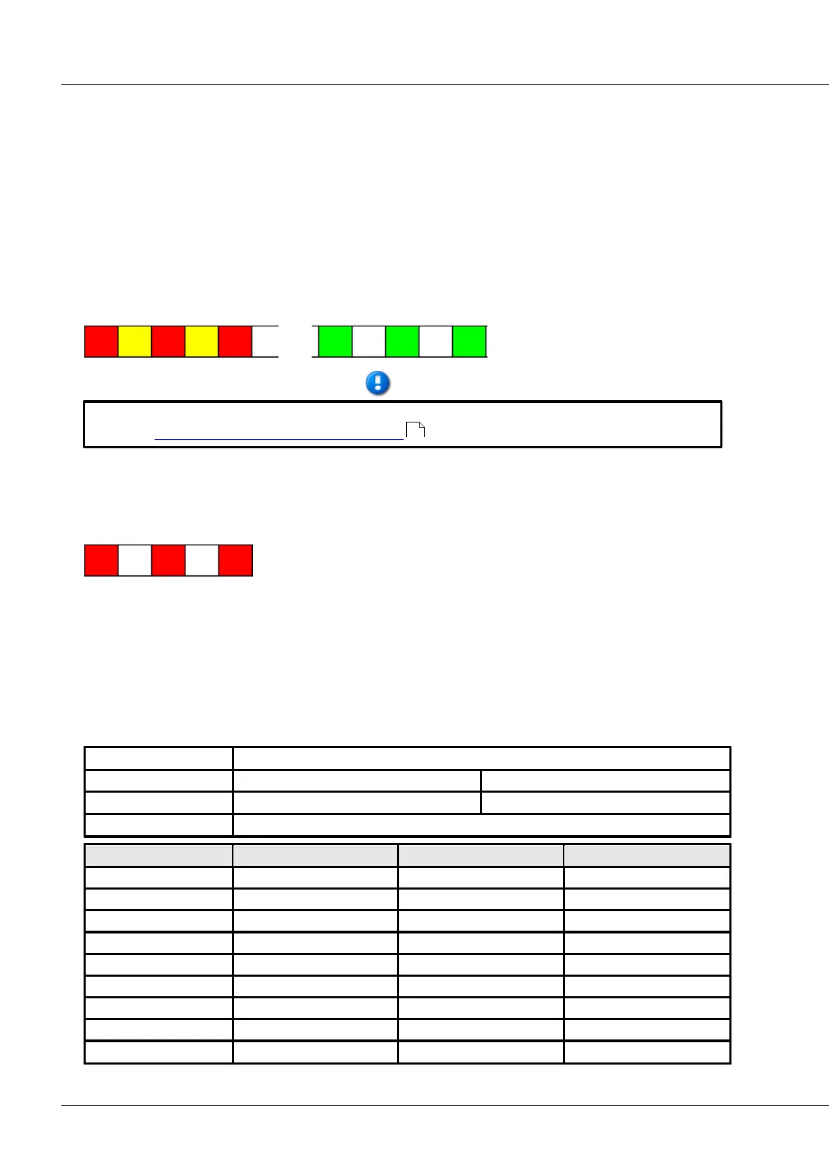
A imc CANSAS device error’s blinking code consists of a sequence of 7 blinks in various colors which
depend on the particular error which occurred. This blinking code is emitted for the whole time, as long
as the device is on.
The error code is commenced with the first three blinking signals in which the LED shines red three times.
The LED’s following four blinking signals make up the actual error code and provide information on the
error’s location and type. In this context, the first two flashes constitute the top-level code (location),
while the last two flashes are the subordinate code (type). The error code’s 7-flash signal is then
repeated.
Same for every error message. Indication that an error occurred.
Flashes for the top-level error code.
Flashes for the subordinate error code.
X and Y can take the following combinations of color values:
223