IGN ignition angle measurement module 333
imc CANSAS Users Manual - Doc. Version 1.9 - 05.12.2014© 2014 imc Meßsysteme GmbH
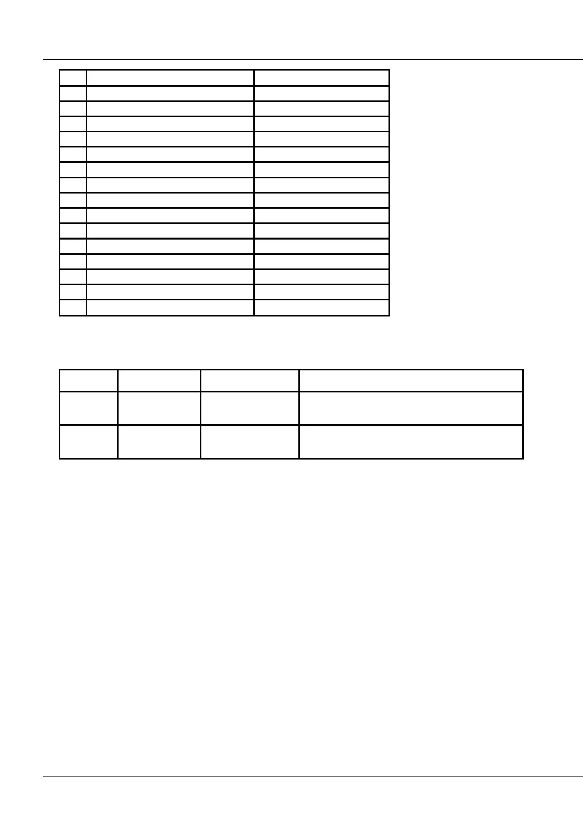
DAC1 AngleOut ( ignition angle)
The analog outputs AngleOut and SpeedOut return voltage signals which are proportional to the ignition
angle and the rotation speed, respectively.
Scaling of the analog outputs:
substitute value: -10 V, if the ignition angle can not
be determined (currently).
substitute value: 0 V, if the ignition angle can not be
determined (currently).
The voltages at the analog outputs must be captured differentially, where the reference is Analog Ground
= Pin 15.
The power supply voltages (5 V and 12 V) are provided for the supply of sensors. For the negative pole,
Pin 13 = Ground is used.
The TTL-outputs (Spark, Crankshaft, REF, CAM) transfer pulses arriving at the inputs Spark and Angle with
a slight delay to TTL-level. So, as reference use Pin 9 = Digital Ground. The delay is due to the analog
conditioning, any digital filtering configured, and the selection of the threshold values.
Pins 9, 10, 11, 12 and 13 are directly connected with each other internally.
Digital Ground and Analog Ground are both at approximately the same voltage level, but slightly de-
coupled from each other by certain electrical components, so that currents through Digital Ground and
the associated voltage drops do not affect Analog Ground and the quality of the analog output signals.
The output REF then only reflects the impulses of the input REF, if an operation mode with a crankshaft
counter having a zero-impulse is selected. Only then is the input REF used at all. In the other operation
modes, the output REF returns one impulse per revolution of the crankshaft. The impulse comes in
response to the first tooth following the gap for counters with a gap missing.
The outputs are not defined in Snapshot mode.