IGN ignition angle measurement module 311
imc CANSAS Users Manual - Doc. Version 1.9 - 05.12.2014© 2014 imc Meßsysteme GmbH
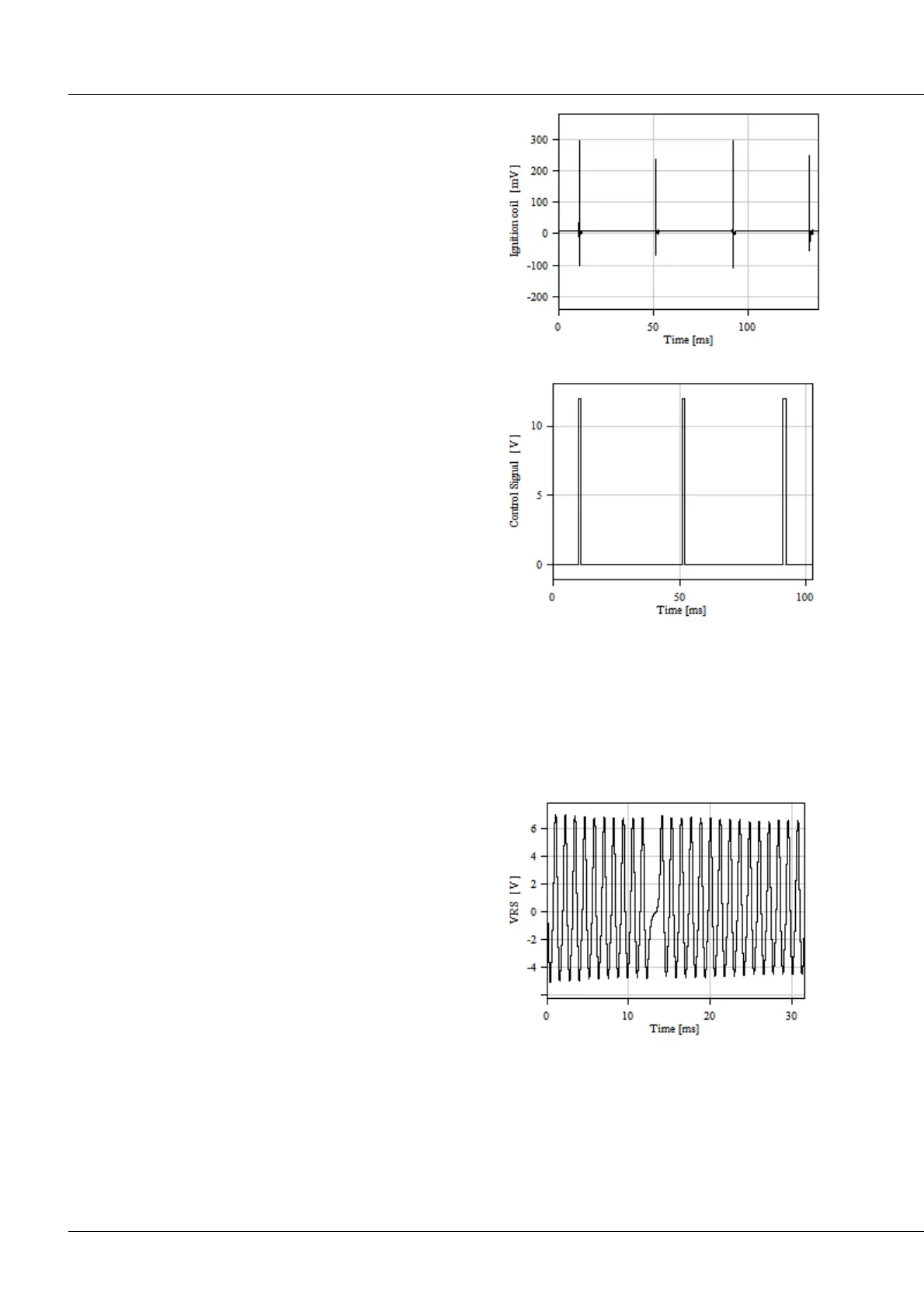
The ignition signal can also be captured at the ignition
coil's primary side by means of a clamp ignition sensor. In
that case the shape is similar, but the signal levels
substantially lower:
Ignition signal: Low level
Direct signal capture at the control lines is also possible. In
that case, this is generally a logic level:
Ignition signal: Logic level
Crankshaft sensor
The reference angle is determined by means of a crankshaft sensor. The sensor determines the
crankshaft's current position, in other words, its angle.
Possible sensors:
The typical case is an inductive approach sensor. this is
the motor's own sensor working by the Variable
Reluctance principle (VRS, variable reluctance sensor).
The sensor samples the flywheel-cogwheel and returns
one pulse per cog. Typically, one or two cogs will be
missing to indicate the zero position. The signal's
amplitude depends on the RPMs.
Motor's nuilt-in inductive pickup (VRS)