318 Properties of the Modules
imc CANSAS Users Manual - Doc. Version 1.9 - 05.12.2014© 2014 imc Meßsysteme GmbH
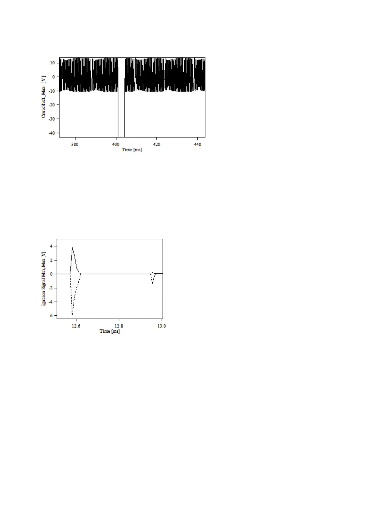
Now it is possible to magnify a segment in order to investigate the missing tooth gap:
Here is shown a magnified except around
the start of a new snapshot. The first valid
measurement value is located to the right
of the positive edge of -43 V (substitute
value 8000H in the gap). The missing tooth
gaps are clearly seen in the actual signal
plot.
For each channel in the snapshot message, there is a minimum and a maximum value. These are needed
in order to evaluate the signal correctly, if a different sampling rate than 3 MHz is stated. For example, if
100 kHz is set, the AD converter will still sample at 3 MHz. One each minimum and maximum value is
generated from every 30 values. By displaying the Min- and Max-values in a curve window, one sees a
"tunnel" through which the actual signal travels. If the tunnel is too wide, then one can assume that
(important) signal components are not being displayed and a higher sampling rate should be chosen.
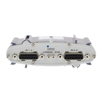
For instance, an ignition signal is sampled at 100 kHz:
Ignition signal with snapshot at 100 kHz
The discrepancy between the Minimum and Maximum is
clearly seen. The true course of the signal is between the
two envelope lines.


 To Next Page