The user interface 71
imc CANSAS Users Manual - Doc. Version 1.9 - 05.12.2014© 2014 imc Meßsysteme GmbH
3.2.4.6.1 Third output module dialog
The structure of the third card is different for data-outputting imc CANSAS modules such as DAC8 or
RDO8R, and depends on whether or not the channel is assigned to a message.
If the channel isn't assigned to any message, the card is empty except for a notice.
If the channel is assigned to a message, the third card contains controls for letting the user define how
the channel's values are to be interpreted from the message.
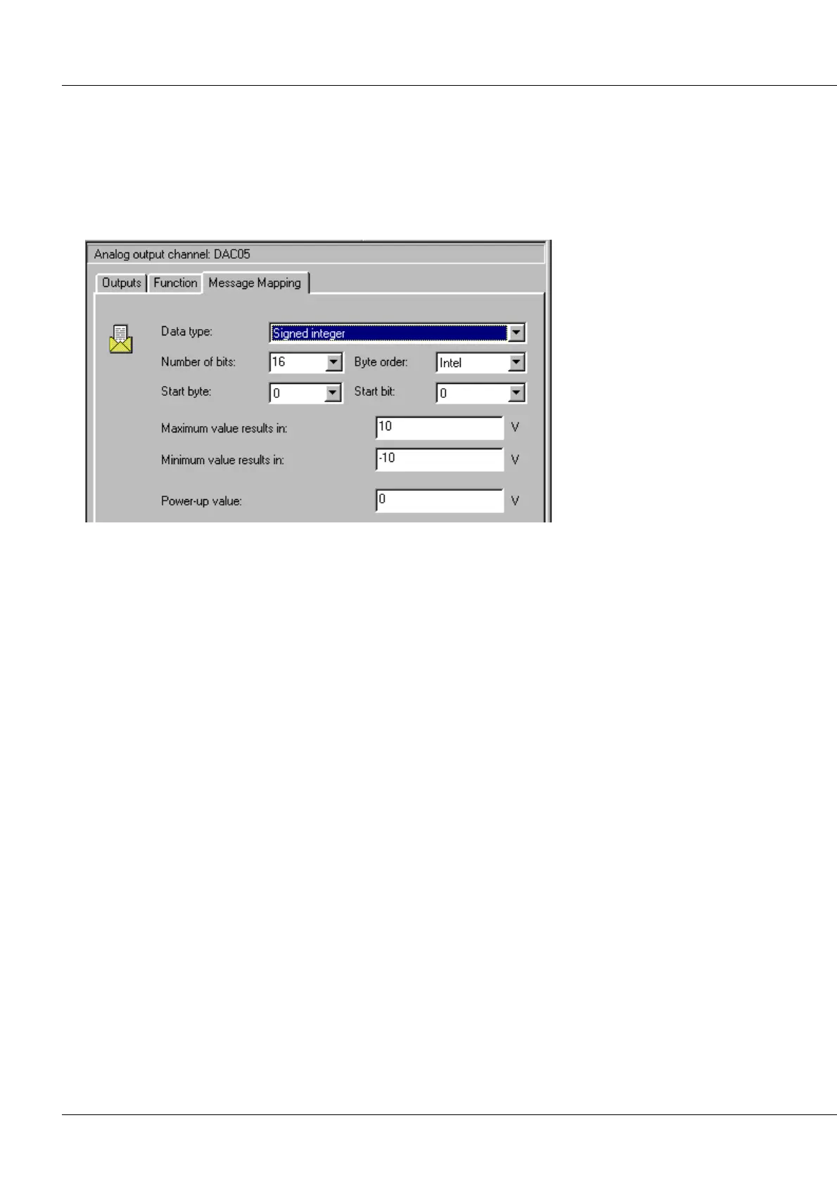
Properties dialog for a CANSAS DAC8 output channel, page 3
Data type: Signed or unsigned integers or digital bits can be read in.
Number of bits: Number of consecutive bits extracted from the message.
Byte order: Intel-Format or Motorola-Format.
Start byte: In which of the message's Bytes does the number begin? Byte 0 is the first Byte transferred in
the CAN-message. Therefore, in an 8-Byte message, 0...7 are available.
Start bit: At which bit in the start Byte does the number begin? Bits 0..7 are possible. Bit 0 is the LSB
(least significant bit), Bit 7 themsB.
Maximum value results in: The maximum binary number which can be extracted from the message is to
be equated to this number.
Minimum value results in: The minimum binary number which can be extracted from the message is to
be equated to this number.
Power-up value: This value is used until the first message arrives. It must be consistent with the above
specifications for the minimum and maximum values.