Causes and corrective actions
PROTECTIVE FUNCTIONS
651
6 5
Alarm
Output is not shut off when a protective function activates. An alarm can also be output with a parameter setting.
(Set "98" in Pr.190 to Pr.196 (output terminal function selection). (Refer to page 384.)
Fault
When a protective function activates, the inverter trips and a fault signal is output.
Operation panel
indication
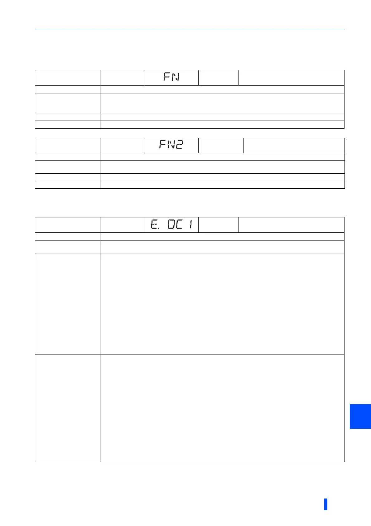
FN FR-PU07 FN
Name
Fan alarm
Description
For the inverter that contains a cooling fan, FN appears on the operation panel when the cooling fan stops
due to a fault, low rotation speed or different operation from the setting of Pr.244 Cooling fan operation
selection.
Check point
Check the cooling fan for a failure.
Corrective action
The fan may be faulty. Please contact your sales representative.
Operation panel
indication
FN2 FR-PU07 FN2
Name
Internal fan alarm (IP55 compatible models only)
Description
FN2 appears on the operation panel when the internal air circulation fan stops due to a fault or low rotation
speed.
Check point
Check the internal air circulation fan for a failure.
Corrective action
The fan may be faulty. Please contact your sales representative.
Operation panel
indication
E.OC1 FR-PU07 OC During Acc
Name
Overcurrent trip during acceleration
Description
When the inverter output current reaches or exceeds approximately 235% of the rated current during
acceleration, the protection circuit is activated and the inverter trips.
Check point
• Check for sudden speed acceleration.
• Check if the downward acceleration time is too long in a lift application.
• Check for output short-circuit.
• Check that the Pr.3 Base frequency setting is not 60 Hz when the motor rated frequency is 50 Hz.
• Check if the stall prevention operation level is set too high. Check if the fast-response current limit operation
is disabled.
• Check that the regenerative driving is not performed frequently. (Check if the output voltage becomes larger
than the V/F reference voltage at regenerative driving and overcurrent occurs due to increase in the motor
current.)
• Check that the power supply for RS-485 terminal is not shorted (under vector control).
• Check that the encoder wiring and the specifications (encoder power supply, resolution, differential/
complementary) are correct. Check also that the motor wiring (U, V, W) is correct (under vector control).
• Check that the rotation direction is not switched from forward to reverse rotation (or from reverse to forward)
during torque control under Real sensorless vector control.
• Check that the inverter capacity matches with the motor capacity. (PM sensorless vector control)
• Check if a start command is given to the inverter while the motor is coasting. (PM sensorless vector control)
Corrective action
• Set the acceleration time longer. (Shorten the downward acceleration time of the lift.)
• If "E.OC1" always appears at start, disconnect the motor once and restart the inverter.
If "E.OC1" still appears, contact your sales representative.
• Check the wiring to make sure that output short circuit does not occur.
• Set 50 Hz in Pr.3 Base frequency. (Refer to page 598.)
• Lower the stall prevention operation level. Activate the fast-response current limit operation.
(Refer to page 348.)
• Set the base voltage (rated voltage of the motor, etc.) in Pr.19 Base frequency voltage.
(Refer to page 598.)
• Check RS-485 terminal connection (under vector control).
• Check the wiring and specifications of the encoder and the motor. Perform the setting according to the
specifications of the encoder and the motor (under vector control). (Refer to page 62.)
• Prevent the motor from switching the rotation direction from forward to reverse (or from reverse to forward)
during torque control under Real sensorless vector control.
• Choose inverter and motor capacities that match. (PM sensorless vector control)
• Input a start command after the motor stops. Alternatively, use the automatic restart after instantaneous
power failure/flying start function. (Refer to page 534.) (IPM sensorless vector control)
Differs according to ratings. The rating can be changed using Pr.570 Multiple rating setting. (Refer to page 265.)
148% for SLD rating,170% for LD rating, 235% for ND rating (initial setting), and 280% for HD rating

 Loading...


