6/02
2-83
DC1632/2240
6-277
Status Indicator RAPs
Prelaunch Training/Review
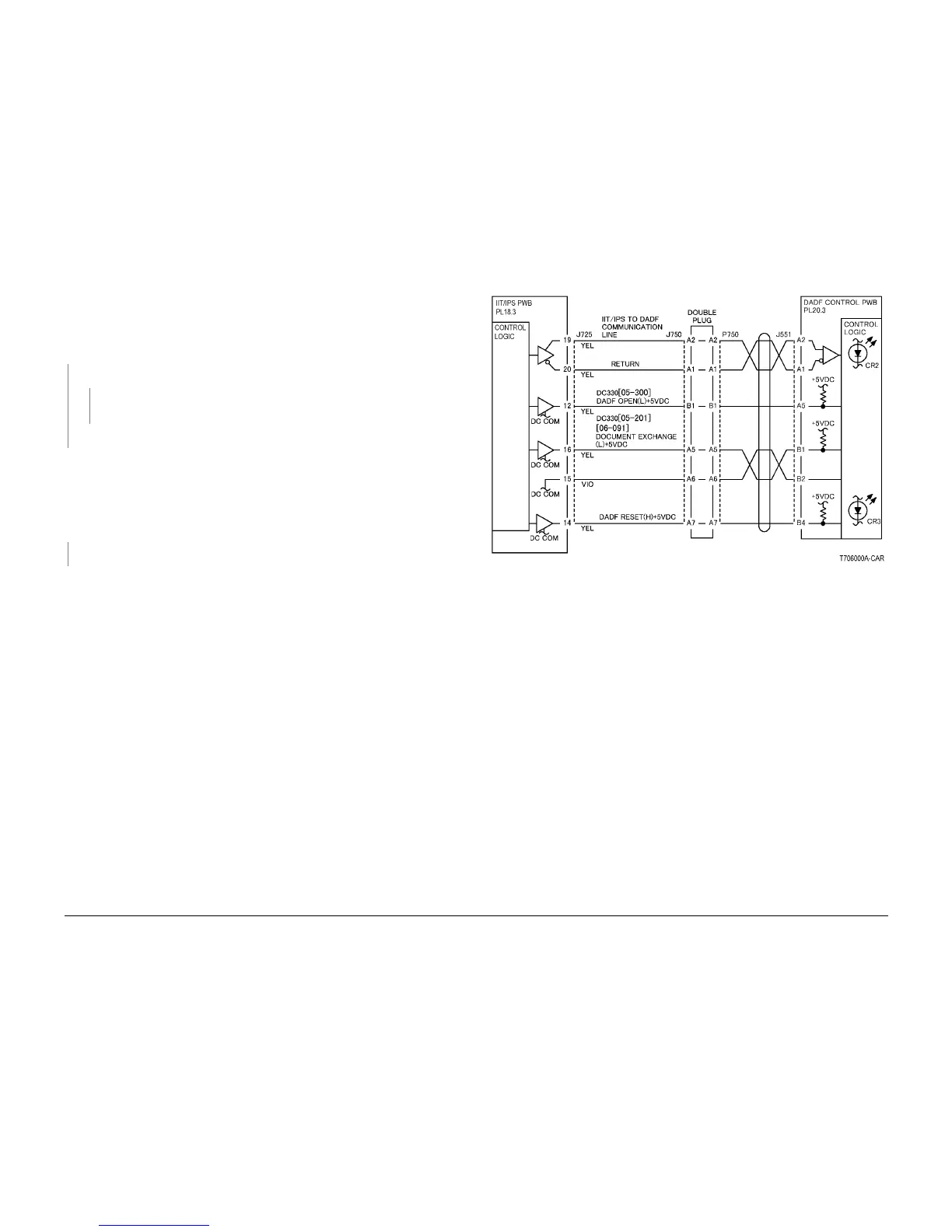
6-277 IISS DADF Communication
Communication cannot be established between the IIT/IPS and the DADF Control PWB.
Procedure
Turn on the power. The CR4 on the DADF Control PWB illuminates.
YN
+5VDC is measured between the DADF Control PWB J550-6 (+) and GND (-).
YN
Check the +5VDC circuit to the DADF Control PWB j550-6 by referring to Chapter 7
Wiring Data (DADF+5VDC)
Replace the DADF Control PWB (PL 20.3).
Turn off the power. Check conductivity of the following:
Between IIT/IPS PWB j725-20 and DADF Control PWB j755-a1
Between IIT/IPS PWB j725-19 and DADF Control PWB j551-a2
Between IIT/IPS PWB j725-18 and DADF Control PWB j551-a3
Between IIT/IPS PWB j725-17 and DADF Control PWB j551-a4
The resistance is 1 Ohm or less for all wires.
YN
Check wires with more than 1 Ohm for an open circuit or poor contact.
Replace the following parts:
DADF Control PWB (PL 20.3)
IIT/IPS PWB (PL 18.3)
Figure 1 IIT DADF Communication CD

 Loading...


