6/02
4-3
DC1632/2240
REP 1.1, REP 1.2
Repairs and Adjustments
Prelaunch Training/Review
REP 1.1 3.3/5 V LVPS Bracket
Parts List on PL 9.1
Removal
WARNING
To avoid personal injury or shock, do not perform repair or adjustment activities with
the power switch on or electrical power applied to the machine.
CAUTION
PWBís can be damaged by an electrostatic discharge. Observe all ESD procedures to avoid
component damage.
1. Remove Rear Cover (REP 14.2).
2. Remove High Voltage Power Supply Chassis (REP 1.6).
3. Release 6 harness clips.
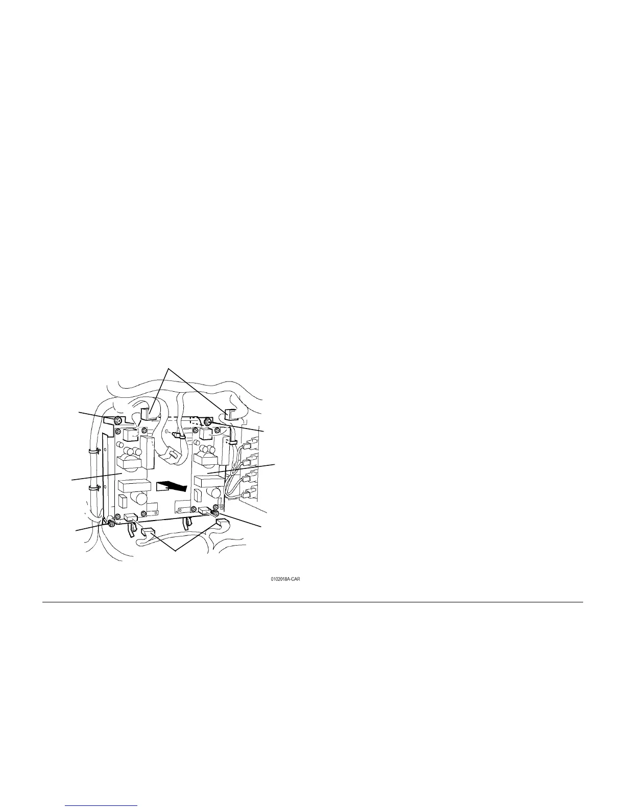
4. Remove 3.3/5 VDC Power Supply Chassis (Figure 1).
a. Disconnect Harness P/Jís (4).
b. Loosen Lower Screws (2).
c. Remove upper Screws (2) and remove 3.3/5 VDC Power Supply Chassis.
Figure 1 Removing 3.3/5 VDC Power Supply Chassis
REP 1.2 MCU PWB
Parts List on PL 13.1
Removal
1. If a new PWB will be installed, record NVM values for new PWB
WARNING
To avoid personal injury or shock, do not perform repair or adjustment activities with
the power switch on or electrical power applied to the machine.
2. Remove Right Cover (REP 14.3).
3. Remove Top Cover (REP 14.1).
4. Remove Rear Cover (REP 14.2).
CAUTION
PWBís can be damaged by an electrostatic discharge. Observe all ESD procedures to avoid
component damage.
5. Remove ESS Chassis (REP 1.3).
6. Remove Screws and remove MCU PWB from ESS Chassis.
Upper
Screw
Upper
Screw
Lower
Screw
Lower
Screw
3.3 VDC
LVPS
5 VDC
LVPS
Harness P/Jís
Harness P/Jís

 Loading...


