6/02
4-170
DC1632/2240
ADJ 9.7, ADJ 9.8
Prelaunch Training/Review
Repairs and Adjustments
ADJ 9.7 IIT Calibration (dC945)
Purpose
ï To calculate and set up the White Reference Correction Coefficient.
ï To correct the IIT sensitivity dispersion (CCD Calibration).
ï Adjust the light axis correction data when replacing the Lens unit.
Adjustment
1. Clean the Optics:
a. Switch off the power and allow the Exposure Lamp to cool off.
b. Using the optical Cleaning Cloth, clean the front and rear of the Document Glass,
Document Cover, White Reference Strip, Reflector, and Mirror.
c. Clean the Exposure Lamp with a clean cloth and Film Remover.
d. Clean the Lens with Lens and Mirror Cleaner and lint free cloth.
2. Connect the PWS to the machine and enter Diagnostic Mode (refer to Entering Diagnostic
Mode using the PWS).
3. Under the Adjustments tab, select Max Setup.
4. Select the IIT Calibration tab.
5. Select the White Reference Adjustment button.
6. Press Start.
7. Follow the instructions on the PWS screen, then select OK.
8. Select the Read button.
9. The setup values are displayed on the White Reference Setup Value screen.
10. When White Reference setup is done, select the CCD Calibration button.
11. Press Start.
12. Follow the instructions on the screen, then select OK.
13. The obtained data is displayed in the b* Calibration Coefficients window.
14. Select [Close] to return to the Color Image Quality Adjustment screen.
NOTE: Do not select Optical Axis Calibration unless replacing the Lens Kit (PL 18.4). Refer to
REP 6.4.
ADJ 9.8 Hard Disk Diagnostics/Setup (dC355)
Purpose
CAUTION
This procedure does not work as described in the current tool; the spec is being rewritten.
This description is an attempt to document the new spec. DO NOT USE.
To perform the diagnostics in the hard disk and setup (initialization) of each partition.
NOTE: Perform this procedure only after the customer's approval is obtained. Check what
kind of data are stored in each partition according to the list below since some partitions store
fonts etc. that the customer has installed.
NOTE: Setup function is only available from customer's mode or UI-Diag mode in Partition A.
Adjustment
1. Connect the PWS to the machine and enter Diagnostic Mode (refer to Entering Diagnostic
Mode using the PWS).
2. Under the Diagnostics tab, select System Test.
3. Select the Hard Disk Diag. Program tab.
4. Select the appropriate Partition (see Table 1.)
5. Select the Diag Type (see Table 2).
6. Press Start.
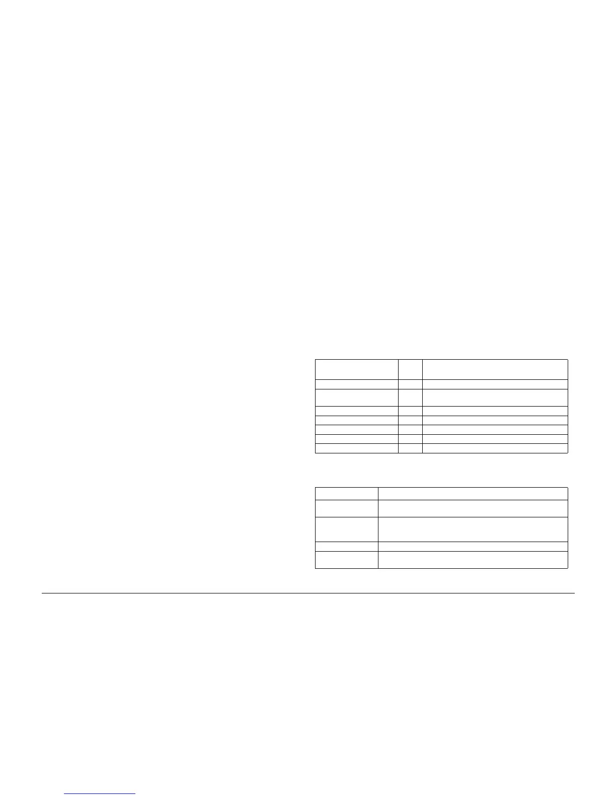
Table 1 Partition Content
Display of appropriate
hard disk column
Size
(GB) Stored information and usages
MP All All All the items in Partition 1~6
MP Partition 1 (a) 2.0 Font, Form/Logo, SMB Folder (Config. txt, driver),
Job Template
MP Partition 2 (b) 2.0 Printing range
MP Partition 3 (c) 1.2 Scan, Report, Mailbox, Security - Print
MP Partition 4 (d) 2.0 PLD, Others
MP Partition 5 (e) 2.0 Copying range
MP Partition 6 (f) 0.5 Spool Cont Control Information, Log
Table 2
Work Item Details
Setup Initialize the file system. It is required when the management data
of the file system corrupts and when read errors occur.
Hard Disk Test
Read Verify)
Perform the Read verify diagnostics of all the sectors in designated
partitions. Sector numbers where a read error is occurring will
appear.
Troubleshooting Perform the hard disk ROM check and controller diagnostics.
Trouble Prediction Perform the SMART (Self-monitoring analysis and reporting tech-
nology) to predict latent troubles on the hard disk.

 Loading...


