6/02
4-169
DC1632/2240
ADJ 9.6
Repairs and Adjustments
Prelaunch Training/Review
4. Select the Center Setup button.
5. Select Start.
CAUTION
Make sure not to hook the wiring harness when moving the MOB Sensor.
6. If Center Setup is OK, dC685 is complete. Use the Cleaning Tool to pull the MOB Sensor
back to the original position, and fasten the screw.
If Center Setup fails, ensure MOB Sensor is positioned to the rear. Go back to step 1 of
the Center check.
Check the Rough Skew Setup
1. Select the Skew (Rough) Setup button.
2. Select Start.
3. Check the Judgement window. If NG is displayed, there is a problem with the ROS, the
IBT Assembly, or the MOB Sensor.
4. If OK is displayed in the Judgement window, check the Skew Correction row in the
Skew Values window. If a value greater than 1 is displayed for any color, perform the
Adjustment, then repeat the Fine Skew Setup check.
Adjustment
1. In the Skew Values window, record the value for each color in the Skew Correction
row. This is the required number of rotations of the adjustment screw.
WARNING
To avoid exposure to laser light, reinstall the Waste Cartridge before attempting to
recheck the adjustment.
2. Remove the Waste Toner Cartridge (REP 9.4).
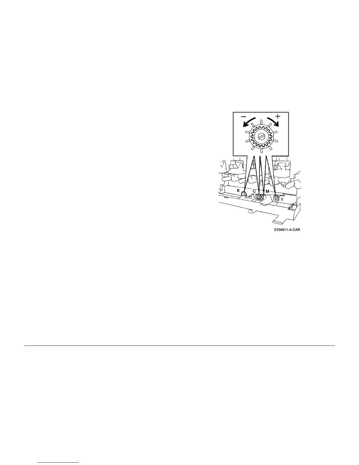
3. For each color, rotate the appropriate (CYMK) adjustment screw (Figure 2) in + (CW), or -
(CCW) direction the number of clicks recorded in step 1.
Figure 2 Adjusting Skew
4. Reinstall Waste Toner Cartridge (REP 9.4).
Check IOT Lead Edge/Side Edge (ADJ 9.9) after performing this adjustment.

 Loading...


