6/02
4-5
DC1632/2240
REP 1.5, REP 1.6
Repairs and Adjustments
Prelaunch Training/Review
REP 1.5 24 V LVPS
Parts List on PL 9.1
Removal
WARNING
To avoid personal injury or shock, do not perform repair or adjustment activities with
the power switch on or electrical power applied to the machine.
1. Remove Rear Cover (REP 14.2).
CAUTION
PWBís can be damaged by an electrostatic discharge. Observe all ESD procedures to avoid
component damage.
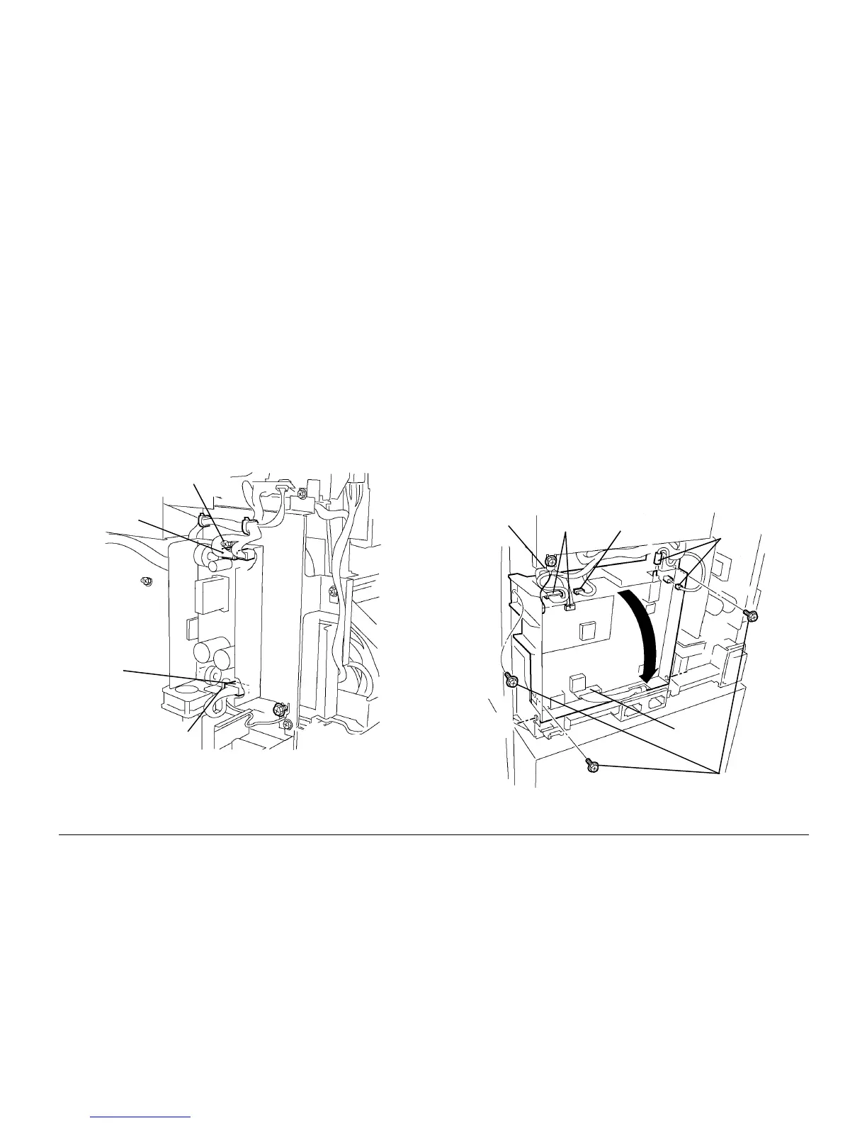
2. Remove 24 V LVPS (Figure 1).
a. Disconnect Harness P/Jís (3).
CAUTION
5 screws with red marks secure LVPS to heat sink. Do not remove them.
b. Loosen Screws (2) and remove LVPS.
Figure 1 Removing 24 VDC Power Supply
REP 1.6 T5 T7 HVPS Chassis
Parts List on PL 9.1
Removal
WARNING
To avoid personal injury or shock, do not perform repair or adjustment activities with
the power switch on or electrical power applied to the machine.
CAUTION
HVPS can be damaged by an electrostatic discharge. Observe all ESD procedures to avoid
component damage.
1. Remove Rear Cover (REP 14.2).
2. Remove High Voltage Power Supply Chassis (Figure 1).
a. Loosen screw and disconnect Ground Wire.
b. Disconnect Harness P/Jís (2). Do not disconnect Soldered Connection
c. Disconnect High Voltage P/J (1).
d. Disconnect High Voltage P/Jís (2).
e. Remove Screws (3).
f. Pivot HVPS down and engage stop strap with frame tab (not shown in figure).
g. Disconnect High Voltage P/J (1) at bottom (not shown in figure).
Figure 1 Removing High Voltage Power Supply
Harness
P/J
Screw
Screw
Harness
P/Jís (2)
Soldered
Connection
Harness
P/Jís (2)
High
Voltage
P/Jís (2)
Screws (3)
High Volt-
age P/J
Ground
Wire

 Loading...


