6/02
3-21
DC1632/2240
Image Quality Specifications
Image Quality
Prelaunch Training/Review
Image Quality Specifications
The following steps are used to set up the machine for the purpose of making test pattern cop-
ies to judge output image color density, balance, and registration.
1. Set the following Customer Mode Settings to the positions listed:
a. Output Color - Full Color
b. Original Type - Photo & Text / Halftone
c. Lighter/Darker - Auto Contrast
d. Variable Color Balance - Normal
e. Color Saturation - Normal
f. Sharpness - Normal
2. Place the Color Test Pattern on the platen. Load 11î X 17 or A3 paper into Tray 1. Make
a copy of the test pattern.
3. Compare the copy to the test pattern. Refer to Figure 2 and Table 1 for this evaluation.
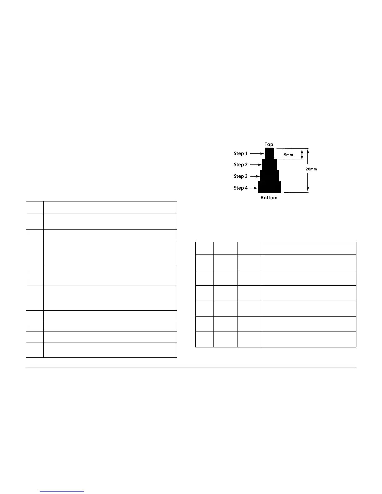
Registration and border deletions are checked using the Step Scales on the Geometric Test
Pattern, an example of which is shown in Figure 1. All of the scales are 20mm in height, and
are made up of four 5mm steps. Step 1 will be described as at the top of the Step Scale, and
Step 4 will be described as at the bottom.
Figure 1 Step Scales
Each Step Scale is positioned for a particular paper size and orientation. Tabl e 2 indicates the
appropriate Step Scales to use for the various paper sizes, orientations and measurement
locations.
1. Set the following Customer Mode Settings to the positions listed:
ï Output Color - Full Color
Table 1 Color Specifications Check Locations
AREA
(Fig. 1)
Check for the Following Results
A Text Reproduction. Each of the seven sentences in this area are fully repro-
duced with no missing letters or portions of letters. The sentences are repro-
duced in Black, Cyan, Magenta, Yellow, Red, Green and Blue.
B Color Registration. The patterns in location B should be properly registered to
provide Black, Red, Green and Blue lines.
C Front to Rear Density. The density of both the low density and high density
bands should be uniform from front to rear. This can be tested by folding the
copy in the center and comparing the front side of the copy to the rear side of
the copy at location C. Both the high density and low density locations should
exhibit even front to rear density.
D Color Gradation. This area should exhibit a decreasing density of each of the
colors from 100% density to 5% density. In a properly adjusted machine, the
10% patches should be visible and the 5% patches should be barely visible or
not visible on the test pattern copy (except for the bottom row).
E Routine Color. Location E represents three general tests for the machine to
reproduce colors common to customer originals.
Location A is a general skin tone test.
Location B represents the color of grass or other common foliage.
Location C represents the color of the sky.
F Photo Gradation. Location F is not used for any copy quality evaluation on
this product.
G IIT Calibration Patches. These patches are scanned for IIT Calibration during
the DC945 IIT Calibration portion of Max Setup.
H 100 Lines/Inch Image. A Moire defect will show on this image. Moire on a 100
Line/Inch image is within specification.
I 175 Lines/Inch Image. This image is used to test for Moire. Depending on the
degree of the defect, moire seen on this image should be considered out of
specification.
Table 2 Geometric Checkout - Step Scale Data.
Paper
Size
Orientation To check: Step Scales to use (refer to Figure 2)
11x17 SEF Lead Edge
Side Edge
Trail Edge
LE1 through LE3
SE1 through SE4 (top); SE5 and SE8 (bottom)
TE3
A3 SEF Lead Edge
Side Edge
Trail Edge
LE 1 through LE3
SE1 through SE4 (top); SE6 and SE7 (bottom)
TE4
8.5x11 SEF Lead Edge
Side Edge
Trail Edge
LE 1 and LE2
SE1 through SE3 (top); SE9 (bottom)
TE5
A4 LSEF Lead Edge
Side Edge
Trail Edge
LE 1 and LE2
SE1 through SE3 (top); SE10 (bottom)
TE6
8.5x11 LEF Lead Edge
Side Edge
Trail Edge
LE1 through SE3
SE1 and 2 (bottom) SE6 and SE7 (top)
TE 2
A4 LEF Lead Edge
Side Edge
Trail Edge
LE1 through SE3
SE5 (top); SE1 and SE2 (bottom)
TE1

 Loading...


