6/02
2-413
DC1632/2240
OF 99-1
Status Indicator RAPs
Prelaunch Training/Review
OF 99-1 Reflective Sensor
Procedure
Enter DC330[XXXX-XXX]. Block the Sensor with a blank sheet of paper. The display
changed.
YN
There is +5VDC measured between the sensor Pin 2 (+) and GND (-).
YN
Check the wire between the sensor Pin 2 and the PWB Pin 8 for an open circuit or a
poor contact. If the check is OK, replace the PWB
There is +5VDC measured between the sensor Pin 1 (+) and Pin 3.
YN
There is +5VDC measured between the PWB Pin 4 (+) and Pin 5.
YN
Replace the PWB.
Check the wire between the PWB Pin 4 and the sensor Pin 1 and between the PWB
Pin 5 and the sensor Pin 3 for an open circuit or a poor contact.
Replace the sensor.
Remove the blank sheet of paper from the sensor. The display changed.
YN
Remove the sensor connector. The display changed.
YN
Check for a short circuit between the sensor Pin 2 and the PWB Pin 8.
If the check is OK, replace the PWB.
Replace the sensor.
Replace the sensor.
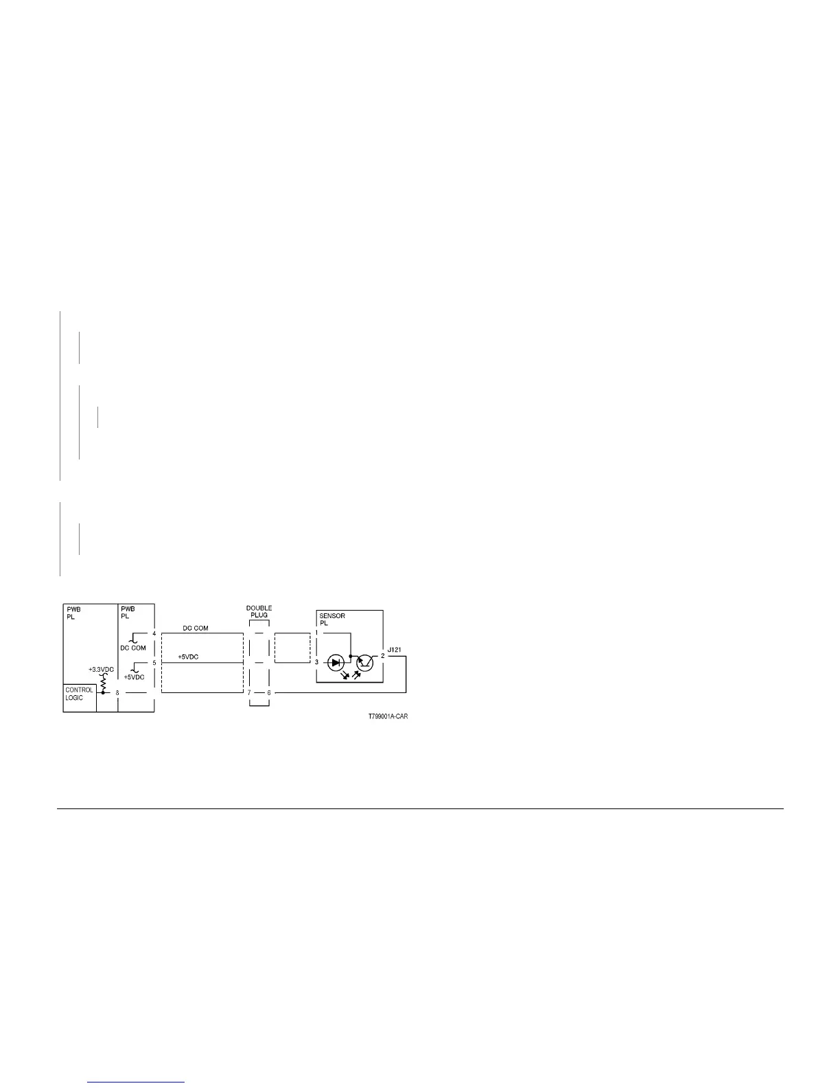
Figure 1 Reflective Sensor CD

 Loading...


