6/02
4-7
DC1632/2240
REP 1.8, REP 1.9
Repairs and Adjustments
Prelaunch Training/Review
Replacement
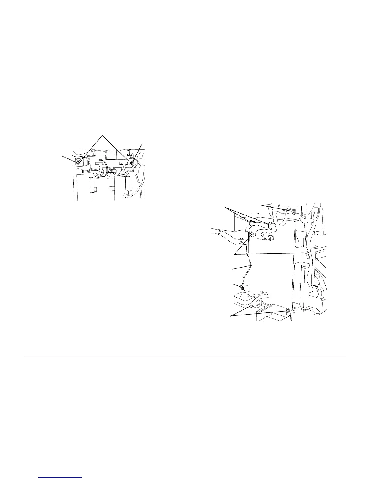
Ensure Screws (2) are positioned in slots as shown before tightening Screws (2) (Figure 2).
Figure 2 Installing Interface PWB
REP 1.9 24 V LVPS Bracket
Parts List on PL 9.1
Removal
WARNING
To avoid personal injury or shock, do not perform repair or adjustment activities with
the power switch on or electrical power applied to the machine.
1. Remove Rear Cover (REP 14.2).
2. Remove Upper Rear Left Cover (REP 14.4).
3. Remove 24 V LVPS (REP 1.5).
4. Remove 24 VDC LVPS Chassis (Figure 1).
a. Remove Top Screw.
b. Remove upper harnesses from Harness Clips (2).
c. Disconnect Fan P/J and remove harness from Harness Clip.
d. Loosen Screws (4).
e. Remove 24 VDC LVPS Chassis.
Figure 1 Removing 24 VDC LVPS Bracket Assembly
Screws (2)
Slot
Slot
Harness
Clips
Harness
Clip
Fan P/J
Screws (2)
Screws (2)
Top
Screw

 Loading...


