6/02
6-79
DC1632/2240
dC612
General Procedures and Information
Prelaunch Training/Review
dC612 Color Test Pattern Print
Purpose
Prints the test patterns in the machine, to help identify Image Quality problems.
Procedure
1. Enter the Diagnostic Mode. Refer to Entering Diagnostic Mode using the PWS.
2. Select Diagnostics in the Service Entry Screen.
3. Select Test Pattern (dc612).
a. To print a Test Pattern, select Image Process System:
i. Select the Pattern Number from the menu.
ii. Select the Paper Tray.
iii. Set the number of prints to output in the Print Count Box and select Start.
b. To print the Image Output Test Pattern, select Image Output System.
i. Image Output System
ii. Paper (Simplex/Duplex)
iii. Paper Tray/Size
iv. Paper Type
v. Screen Type
vi. Color Mode
vii. Set the number of prints to output and select Start.
Test Patterns
CAUTION
The patterns currently displayed do not match the descriptions in the table. The correct pattern
number/descriptions are TBD.
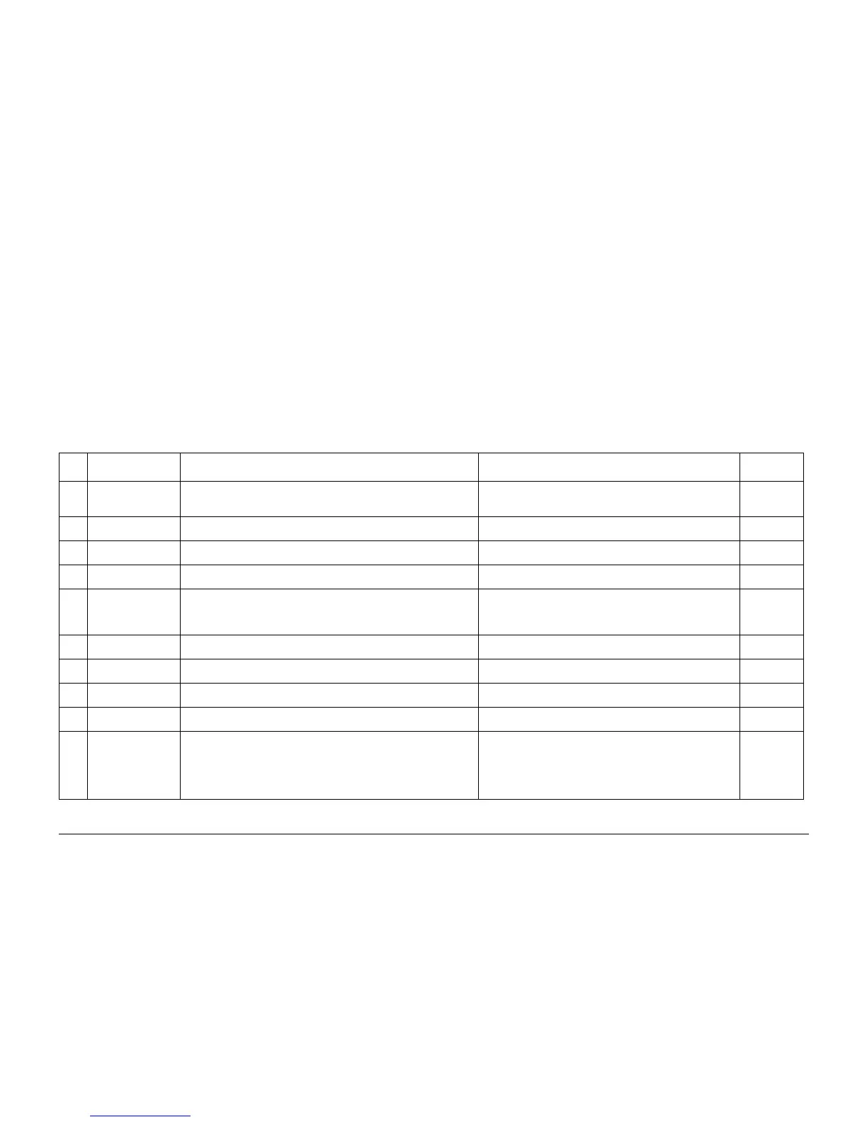
For details on the test pattern generation location and output path, see Table 1:
Table 1 Test Patterns
Patte
rn # Pattern Name Overview Purpose Location
1 ROS Check Seal Glass Cleaning Guide: 20% Half Tone Full Band Width KCMRY Fast
Scan direction Stripe Pattern
The engine where defect has occurred can be determined as an
output sheet contains Seal Glass smearing. -> To determine defect
engine
IOT
2 Halftone (IOT) Seal Glass Cleaning Guide: 20% Half Tone Full Band Width Full Half Tone.
Select the density from Cin=0~100.
Defect can be detected/evaluated (streaks, uneven density, band-
ing)
IOT
3 Grid 1dot (For separating troubles) 512 dot Pitch Grid Pattern with 1 dot width - Around Alignment and Color Regi
- Secondary Transfer part magnification failure
IOT
4 Fast Scan 8 Gradation (For separating troubles) Fast Scan direction 8 Gradation Pattern For development.
For ASIC debug.
IOT
5 A1 Patch Forms a bi-axial near the IN and OUT edges in full color. (Chevron Pattern)
At normal Regi Control cycle: Approx. half cycle of IBT Belt (2 sheets of A4
continuous) At Diag Regi Control cycle: Approx. 1 cycle of IBT Belt (1: 4
sheets of A4 continuous)
For Color Regi adjustment in Diag DC685-1 (Skew Fine Setup)
and DC685-2 (In/Out Setup) during JOB, at beginning of JOB and
end of JOB. Also, for Color Regi reading in DC681 and DC684.
Controller
6 A2 Patch Forms a 1 axial near CNT for approx. 1 cycle (1: 4 sheets of A4 continuous)
of IBT Belt in full color. (Chevron Pattern)
For Color Regi adjustment in Diag DC685-3 (Center Setup) Controller
7 B1 Patch Forms a bi-axial near the IN and OUT edges for approx. 1 cycle (1: 4 sheets
of A4 continuous) in full color. ("<" pattern)
For Color Regi rough adjustment in Diag DC685-1 (Skew Fine
Setup) and 685-4 (Skew Rough Setup).
Controller
8 B2 Patch Forms a 1 axial near CNT for approx. 1 cycle (1: 4 sheets of A4 continuous)
of IBT Belt in full color. ("<" pattern)
For Color Regi adjustment in Diag DC685-3 (Center Setup) Controller
9 C Patch Forms a three-axle IN/CNT/OUT in approx. 1 cycle (1: 4 sheets of A4 contin-
uous) of IBT Belt in single color C. (Chevron Pattern)
For Diag DC683 (to check Sensor, Cyan and position shift). Controller
10 Binary/Auto Gradation
Correction PG (For
Printer) LUT: C-TRA
OFF IOT OFF
(For gradation correction) Gradation pattern for gradation correction for
printing LUT: C-TRA OFF IOT OFF
To output during Auto Gradation Correction. For checking
CTRACS feature. The same pattern as this output pattern is even
output in the CTRACS feature (Reads the output pattern by IIT
and sets up the color reproducibility) inside the Tools (opened to
customer). The test pattern here is able to check the setup effects
of the Printer feature.
Controller

 Loading...


