6/02
6-70
DC1632/2240
dC305, dC330
Prelaunch Training/Review
General Procedures and Information
dC305 UI Component Check
Purpose
Checks the operations of the UI Screen and Control Panel buttons.
Procedure
1. Enter the Diagnostic Mode. Refer to Entering Diagnostic Mode using the PWS.
2. Select the Diagnostics Tab in the Service Entry Screen.
3. Select the System Test Tab in the Diagnostics Screen. The System Test Screen displays.
The UI Component Check dC305 is the default screen.
4. Select Start. The following message displays, Perform the UI Component Check on
the Machine. When complete, select Stop.
5. Select OK.
6. Touch the UI Screen in a different locations. The highlighted point moves to the new loca-
tion.
7. All LEDs should be illuminated when the dC305 Touch Screen Test is displayed. Select
Stop to Turn-OFF all LEDs.
8. Select Stop on the Component Check Screen.
9. The Touch Screen Test Screen on the machine UI closes.
dC330 Component Control
Purpose
The purpose of the dC330 Component Control is to display the logic state of input signals and
to energize output components.
NOTE: Refer to Table 1 for a list of all Input Components listed by Chain/Link ID number.
Refer to Table 2 for a list of all Output Components listed by Chain/Link ID number.
Procedure
1. Enter the Diagnostic Mode. Refer to Entering Diagnostic Mode using the PWS.
2. Select the Diagnostics Tab on the Service Entry Screen.
3. Select Component Control (dC330) on the Diagnostic Entry Screen.
4. The dC330 Screen is displayed. The display indicates the following:
ï Input/Output Components
ï ID Number (chain/function order)
ï Active Stack (including ID and state of component)
NOTE: The Component Control Codes can be selected in categories by their related sys-
tem, such as: Processor, System, Sorter / OCT / Mailbox, Finisher, DADF, HCF and ITT.
5. Activate the desired component code by double clicking on the Chain/Link ID number or
by clicking once on the Chain/Link ID number then selecting the Start Button. The IDís
will display in the Active Stack.
6. Press the Stop button or double click the active component in the active stack box to
end the test. The ID and Active Stack components are removed from the Active Stack
box.
Stacking Component Codes
1. To stack several codes, select the first code and press Start, then select the next code
and press Start. Continue to enter up to eleven codes.
2. The selected ID appears in the ID column of the Active Stack box and the state changes
to Run; H or L as applicable.
3. Stop a highlighted component by pressing Stop or double click the active component in
the Active Stack Box
4. To switch Off all components and clear the screen, press Stop All.
NOTE: Components that are currently running are shaded in Green. Components that have
been run are shaded in Yellow.
NOTE: When exiting dc330, the machine resets and communication between the PWS and
the machine is momentarily lost. The PWS will reconnect automatically.
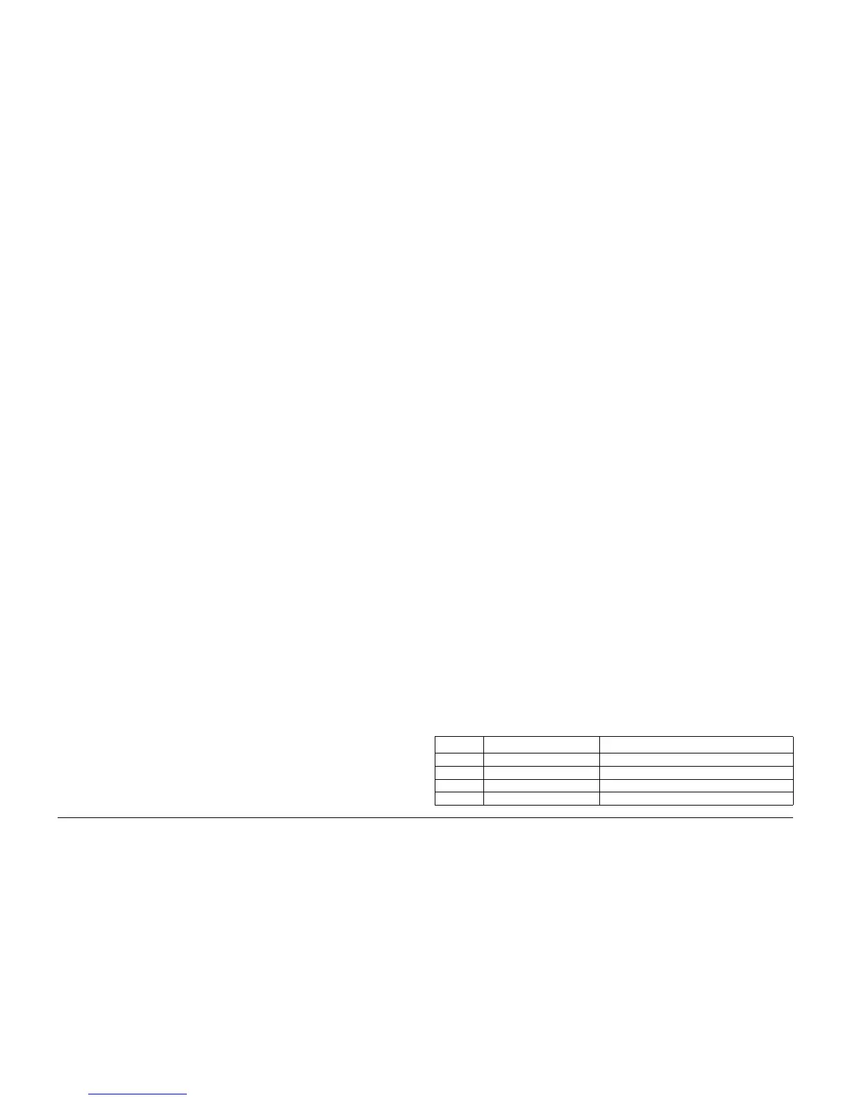
Table 1 Input Component Control Codes
Code Name Description
001-300 INTLK_1 High when Open is detected. ON: High
001-301 INTLK_2 High when Open is detected. ON: High
001-302 LH LOW I/L SW High when Open is detected. ON: High
001-304 LH 3TM I/L SW Low when Open is detected. ON: Low

 Loading...


