6/02
4-15
DC1632/2240
REP 4.4
Repairs and Adjustments
Prelaunch Training/Review
REP 4.4 Drum Motor Assembly
Parts List on PL 1.1
Removal
WARNING
To avoid personal injury or shock, do not perform repair or adjustment activities with
the power switch on or electrical power applied to the machine.
1. Remove Right Cover (REP 14.3).
2. Remove Top Cover (REP 14.1).
3. Remove Rear Cover (REP 14.2).
CAUTION
Machine problems will result from careless harness routing during reassembly. Carefully
observe position of wiring harnesses for later reinstallation.
NOTE: Step 6 can be omitted if Low Voltage Power Supply P/Jís are disconnected before per-
forming step 7.
4. Remove 24 V LVPS (REP 1.5).
5. Remove 24 VDC LVPS Chassis (REP 1.9).
6. Remove Control Chassis (REP 1.3).
7. Remove High Voltage Power Supply Chassis (REP 1.6).
NOTE: In next step, do not disconnect P/Jís.
8. Loosen Interface PWB chassis mounting screws (2) and move chassis up (REP 1.8).
9. Remove Photoreceptor Module Drive Motor (REP 4.2).
10. Remove Developer High Voltage Power Supply (REP 1.10).
11. Remove 3.3/5 VDC Power Supply Chassis (REP 1.1).
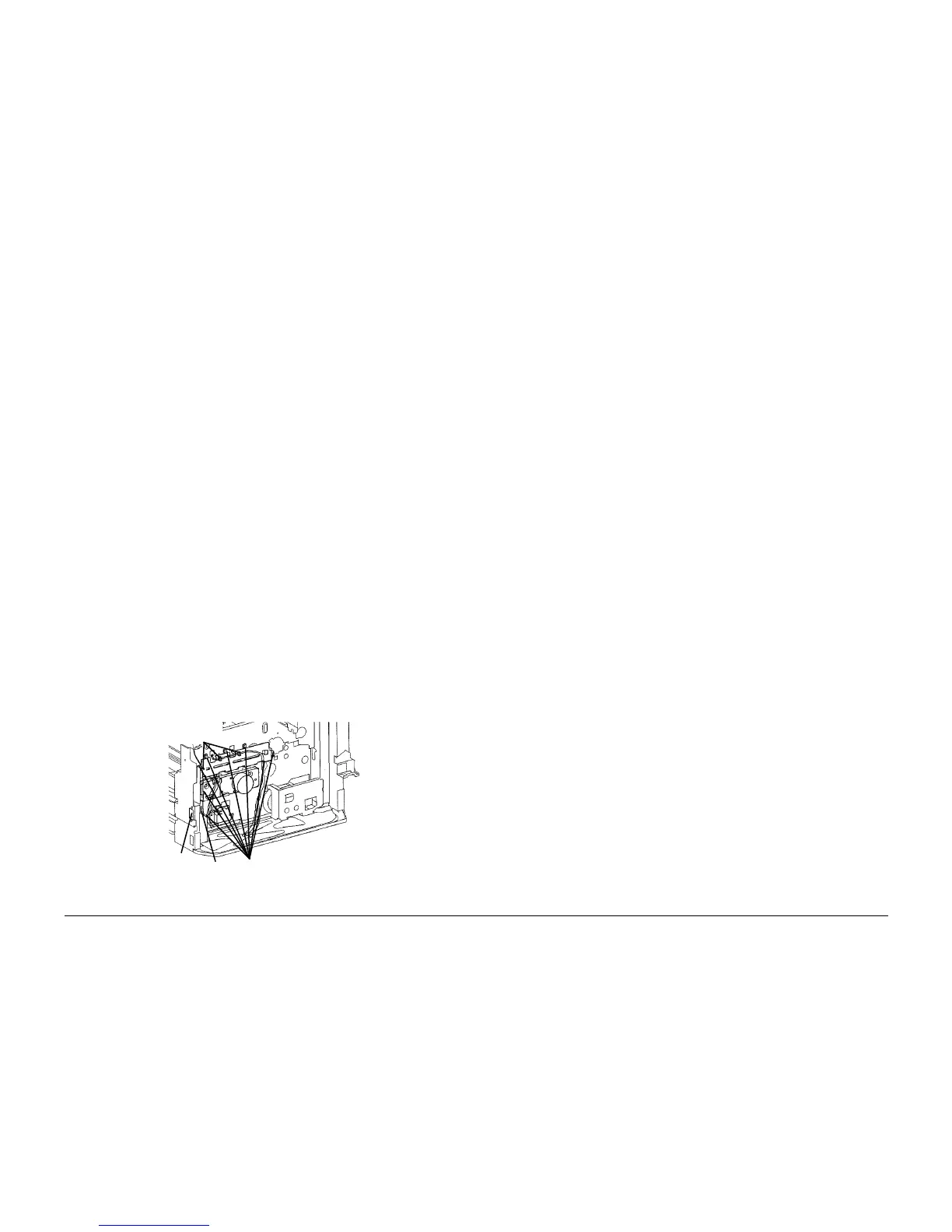
12. Remove Print Cartridge Drive Module (Figure 1).
a. Release harness from Harness Clips (3)
b. Remove screws (2) to release Connector from frame.
c. Disconnect P/J.
d. Remove Screws (8) and remove Print Cartridge Drive Module.
Figure 1 Removing Print Cartridge Drive Module
Harness
Clips (3)
Con-
nector
P/J
Screws (8)

 Loading...


