6/02
2-371
DC1632/2240
116-324, 116-325
Status Indicator RAPs
Prelaunch Training/Review
116-324 Exception Error
CPU exceptional error.
Procedure
Switch power off then on. The problem continues.
YN
Return to Service Call Procedures.
Replace the ESS PWB (PL 13.1).
116-325 Communication Error
+24 VDC enabled Communications failure.
Procedure
+24 VDC power is failed. Status Code 102-319 is displayed after 116-325 is displayed.
YN
Preliminary information not available.
+24V LVPS is failed. Perform following:
ï Remove Rear Cover (REP 14.2).
ï Remove cover from +24V LVPS (PL 9.1).
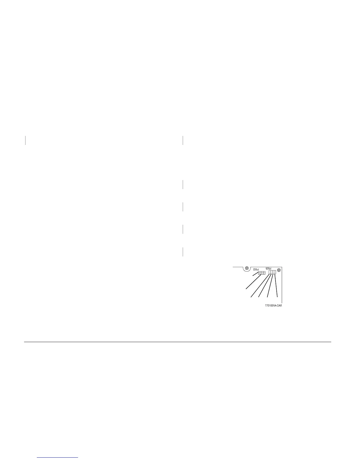
ï Disconnect P502 on +24V LVPS (Figure 1).
Check that power is switched off. Measure resistance of fuse on +24V LVPS. Resistance is 1
ohm or less.
YN
Replace +24V LVPS (PL 9.1).
Switch on the power. Measure the AC voltage between the white and black wires in P2 on the
+24 VDC. 110 or 220 VAC is measured.
YN
Go to the AC Power RAP.
Connect the black meter lead to DC COM or frame. Measure DC voltage at P505 on the +24 V
LVPS (Figure 1). Voltages are measured as shown.
YN
There is a problem with the +24 VDC enable circuit. Go to the +24 VDC Enable RAP.
Measure the DC voltage at P502 on the +24V LVPS (Figure 1). Voltages are measured as
shown.
YN
Replace the 24V LVPS (PL 9.1).
There is a short circuit in +24 VDC distribution. Go to the +24 VDC Short Circuit RAP.
Figure 1 P502, P505 on +24V LVPS
+24V, 0V, +3.5V, +5V
+24 VDC RET
Vio (all on top)
+24 VDC
Orn (all)

 Loading...


