6/02
4-35
DC1632/2240
REP 5.16
Repairs and Adjustments
Prelaunch Training/Review
REP 5.16 Exit Motor Assembly
Parts List on PL 20.9
Removal
WARNING
To avoid personal injury or shock, do not perform repair or adjustment activities with
the power switch on or electrical power applied to the machine.
1. Remove Rear Cover (REP 5.18).
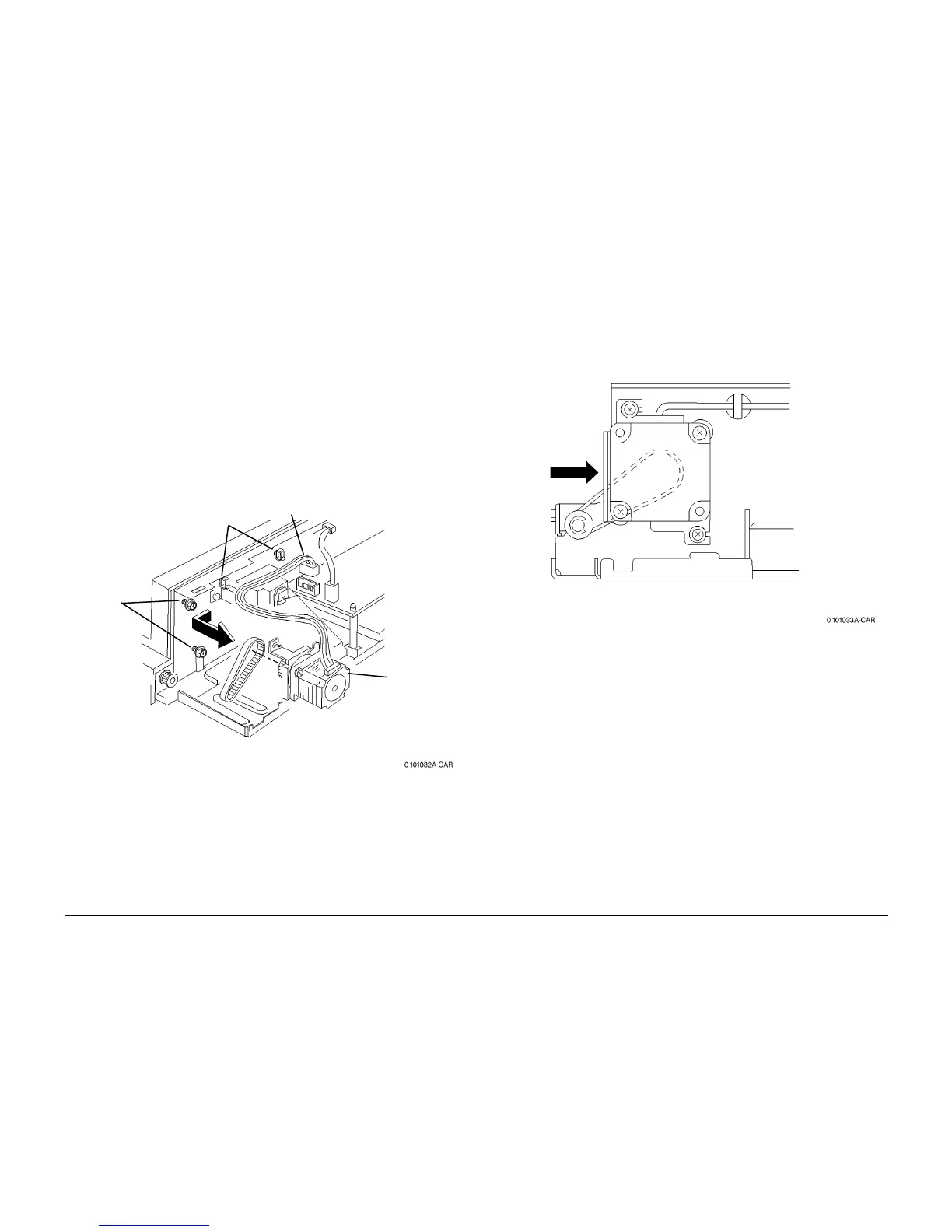
2. Remove Exit Motor Assembly (Figure 1).
a. Disconnect connector.
b. Release clamps (2) and remove wire.
c. Loosen screws (2).
d. Remove belt.
e. Remove Exit Motor Assembly.
Figure 1 Removing Exit Motor Assembly
Replacement
NOTE: Belt should be tight but not stretched before tightening motor mounting screws (Figure
2).
Figure 2 Tightening Exit Motor Assembly Mounting Screws
1
Disconnect
2
Release wires
from Clamps
3
Loosen
Screws (2)
4
Remove
Exit Motor
Assembly
and Belt
 Loading...


