6/02
2-187
DC1632/2240
10-353
Status Indicator RAPs
Prelaunch Training/Review
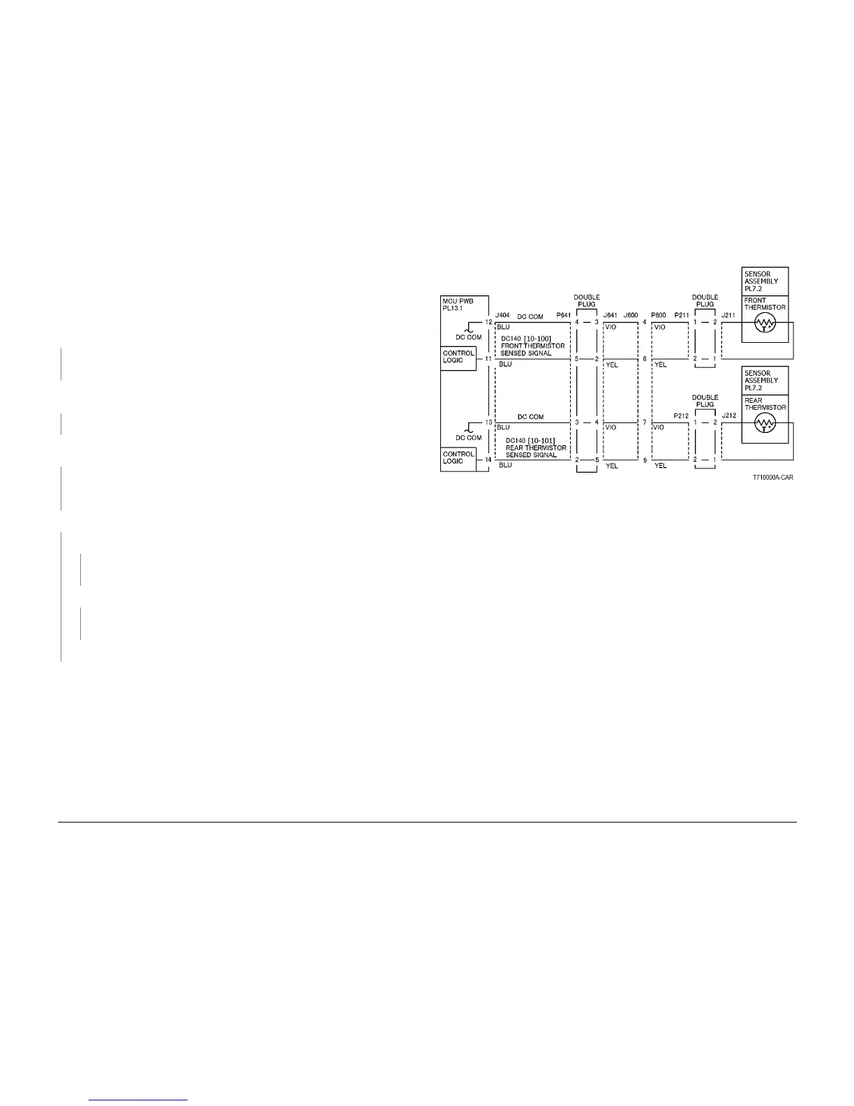
10-353 Main Heater On Time
The Main Heater remained on for more than the specified time.
Procedure
Turn off the power, remove the Fuser Assembly. and allow it to cool down.
Measure the resistance between P/J600-4 and P/J600-6 on the Fuser Assembly.
The resistance is between 30 and 190 K Ohmís.
YN
Check the Front Thermistor for an open circuit and poor contact. If the check is OK,
replace the Sensor Assembly (PL 7.2).
Measure the resistance between P/J600-3 and P/J60012 on the Fuser Assembly. The resis-
tance is 20 Ohmís or less.
YN
Replace the Fuser Assembly (PL 7.2).
Reinstall the Fuser Assembly, turn the power on, enter dC140 [010-100]. The display is
between 676 and 699.
YN
Turn the power off. Check for an open or poor connection between P/J404-12 on the MCU
PWB and P/J600-6 on the Fuser Assembly. If the check is OK, replace the MCU PWB (PL
13.1).
There is Line Voltage measured at FS41 on the AC Drive PWB (PL 9.2).
YN
There is +5VDC measured at P/J590-5 on the AC Drive PWB (PL 9.2).
YN
Check the wires and connectors. If the check is OK, replace the MCU PWB (PL
13.1).
There is +24VDC measured at P/J590-1 on the AC Drive PWB PL 9.2.
YN
Check the wires and connectors. If the check is OK, replace the MCU PWB (PL
13.1).
Replace the AC Drive PWB (PL 9.2).
Check the wires and connectors. If the check is OK, replace the Fuser Assembly (PL 7.1).
Figure 1 Fuser Front and Rear Thermistor CD
 Loading...


