6/02
2-209
DC1632/2240
12-253
Status Indicator RAPs
Prelaunch Training/Review
12-253 Rear Tamper
ï With the Rear Tamper Home Sensor off The Rear Tamper Home Sensor did not turn on
within 800ms after move to the Rear Tamper Home position has begun.
ï With the Rear Tamper Home Sensor on: The Rear Tamper Home Sensor did not turn off
when the Rear Tamper Home Sensor is deactuating.
Procedure
Enter dC330 [012-010] (front) or [12-013] (rear) and press Start. The Rear Tamper Guide
energizes.
YN
The Rear Tamper Motor energizes.
YN
+24 VDC is measured between J848-B1 or B3 or B4 or B6 on the Finisher PWB
and Finisher PWB Chassis (-).
YN
+24 VDC is measured between J848-B2 or B5 on the Finisher PWB and
Finisher PWB Chassis (-).
YN
Replace the Finisher PWB (PL 17.13).
Check the wire between the Finisher PWB p/j and the Rear Tamper Motor p/j
for a short circuit, open circuit, or poor contact.
If the wires and connections are good, replace the Front Tamper Motor (PL
17.10).
Replace the Finisher PWB (PL 17.13).
Check the tamper mechanism for load or drive transmission failure (gear wear or break-
age).
Enter dC330 [012-212] and press Start. Move the Rear Tamper manually and turn the Rear
Tamper Home Sensor on/off. The display changes.
YN
Check the Rear Tamper Home Sensor using the Generic Transmissive Sensor RAP.
Replace the Finisher PWB (PL 17.13).
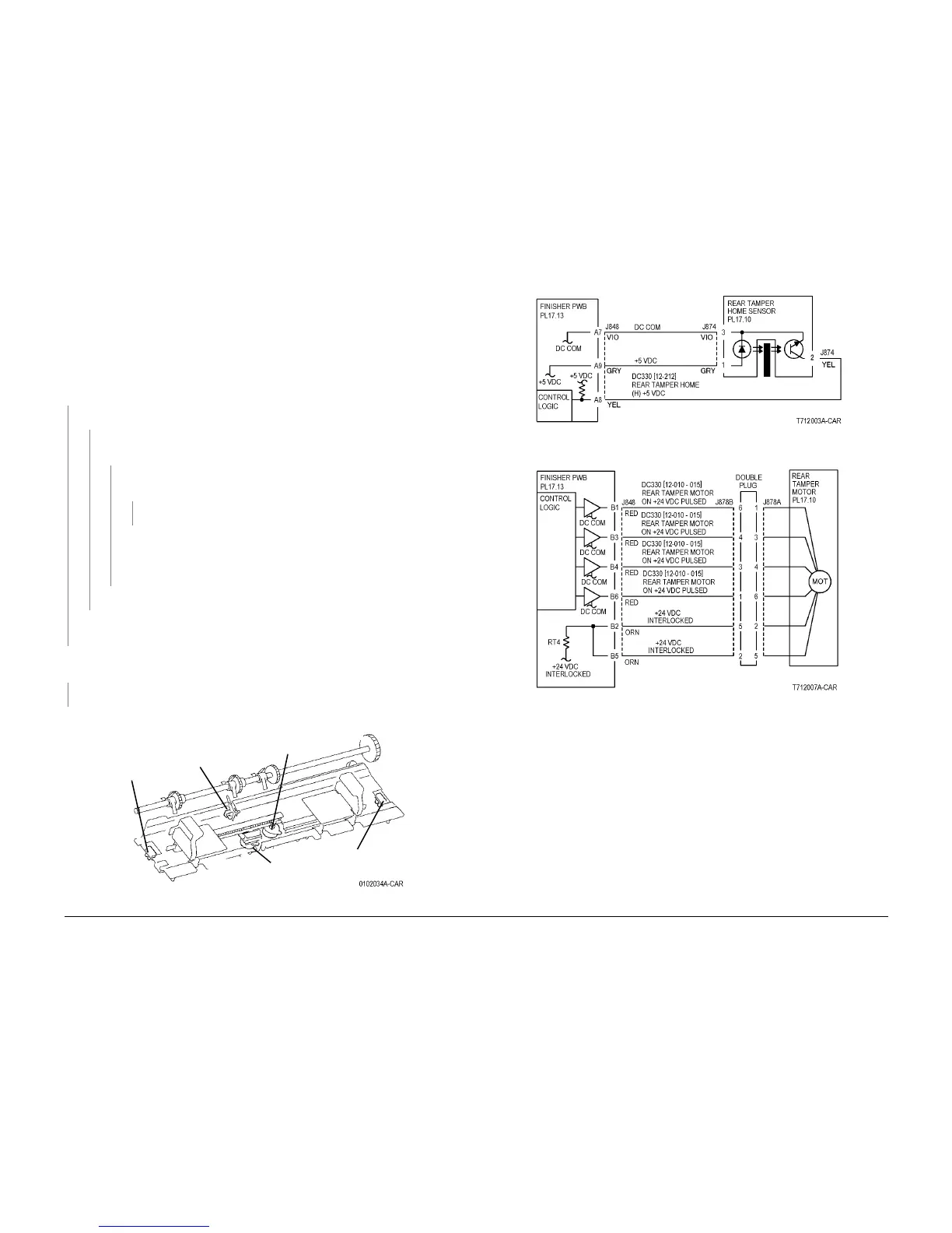
Figure 1 Component Location
Figure 2 Rear Tamper Home Sensor CD
Figure 3 Rear Tamper Motor CD
Rear Tamper
Home Sensor
Front
Tamper
Home
Sensor
Front Tamper Motor
Connection
Rear Tamper Motor
Connection
Compiler
Paper
Sensor

 Loading...


