6/02
2-409
DC1632/2240
OF 1-1
Status Indicator RAPs
Prelaunch Training/Review
OF 1-1 +3.5 VDC
+3.5 VDC failure.
Procedure
Perform following:
ï Remove Rear Cover (REP 14.2).
ï Tilt out HVPS Chassis (REP 1.6).
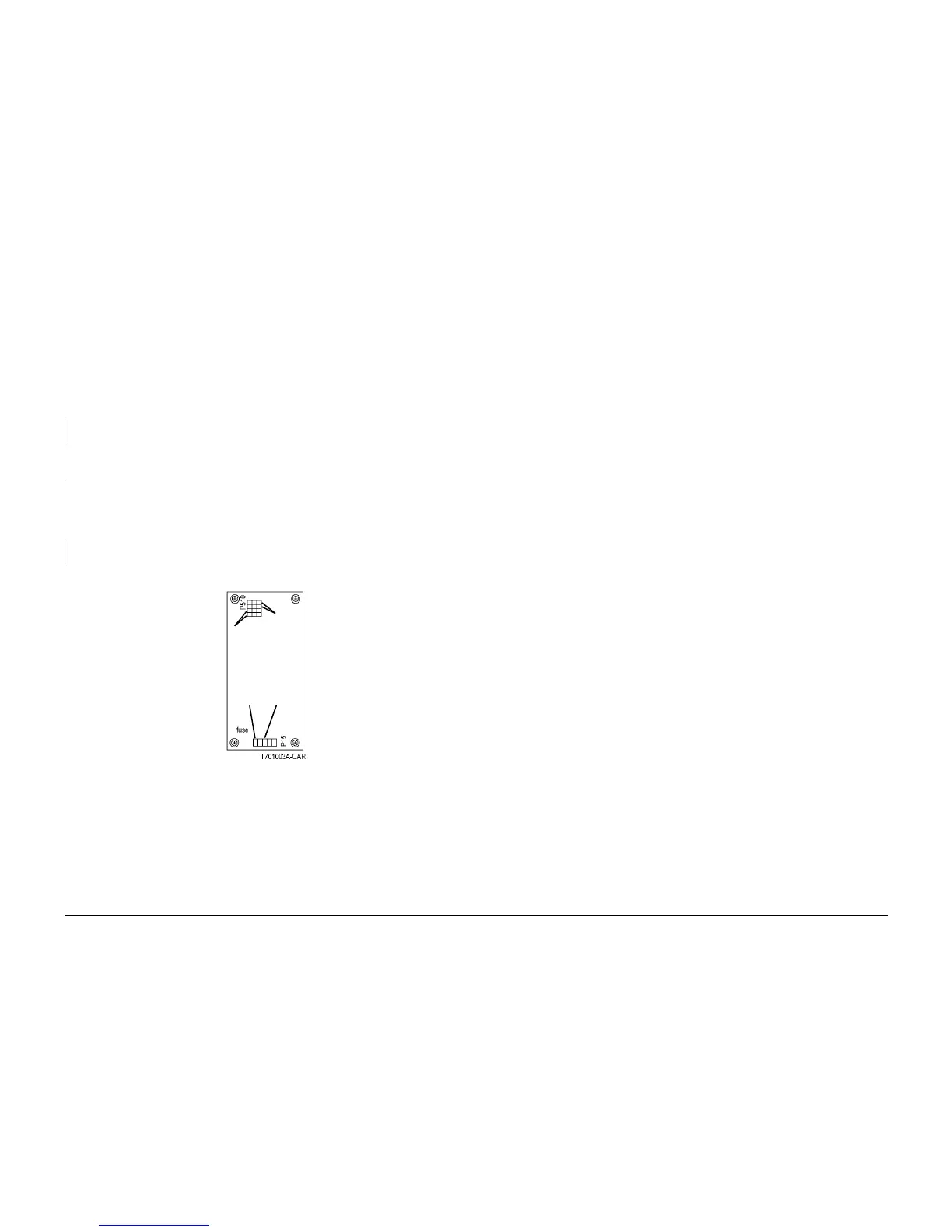
Check that power is switched off. Measure resistance of fuse on +3.5V LVPS (Figure 1).
Resistance is 1 ohm or less.
YN
Replace +3.5V LVPS (PL 9.1).
Switch on the power. Measure the AC voltage between the white and black wires in p15 on the
+3.5V LVPS (Figure 1). 110 or 220 VAC is measured.
YN
Go to the AC Power RAP.
Connect the black meter lead to DC COM or frame. Measure DC voltage at p510 on the +3.5
V LVPS (Figure 1). Voltages are measured as shown.
YN
Replace the 3.5V LVPS (PL 9.1).
There is a short circuit in +3.5 VDC distribution. Go to the +3.5 VDC Short Circuit RAP.
Figure 1 P15, P510 on +3.5V LVPS
+3.5
VDC
RET
Vio
+3.5
VDC
Gry
Black
Wire
White
Wire

 Loading...


