3 Analog I/O Modules
30-22 WindO/I-NV4 User’s Manual
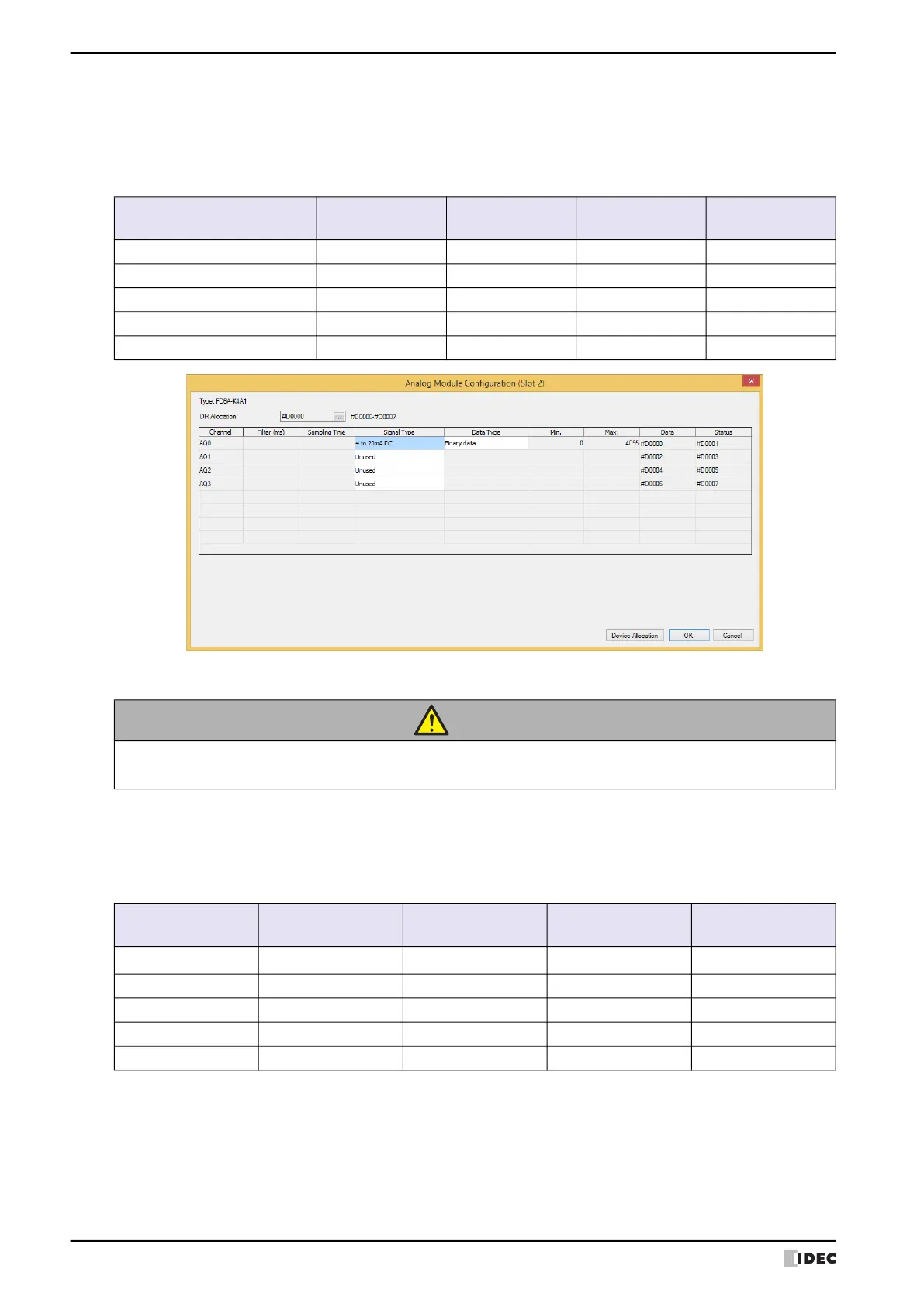
● Analog Output Type
The following parameters are for configuring the analog outputs on the analog output modules and the mixed analog
I/O modules.
YES: Supported, NO: Not supported
■ Signal Type
The signal type that can be set differs according to the analog I/O module model. Select the analog I/O module that
corresponds to the user application and set the signal type. There are five types of signal types for the analog
outputs, which are detailed as follows.
YES: Supported, NO: Not supported
*1 Channels that are set to Unused are not scanned. A channel set to unused always outputs 0 V.
The circuit is setup the same as when 0 to 10V DC is selected as Signal Type.
Parameter
FC6A-K2A1
FC6A-K2A4
FC6A-K4A1
FC6A-K4A4
FC6A-L06A1
FC6A-L06A4
FC6A-L03CN1
FC6A-L03CN4
Signal Type YES YES YES YES
Data Type YES YES YES YES
Minimum and Maximum values YES YES YES YES
Data YES YES YES YES
Status YES YES YES YES
CAUTION
The device connected to the analog I/O module may be damaged if the analog output signal type is
mistakenly set and used. Please use caution when setting the analog output signal type.
Signal Type
FC6A-K2A1
FC6A-K2A4
FC6A-K4A1
FC6A-K4A4
FC6A-L06A1
FC6A-L06A4
FC6A-L03CN1
FC6A-L03CN4
Unused
*1
YES YES YES YES
0 to 10V DC YES YES YES YES
-10 to +10V DC YES YES YES YES
0 to 20mA DC YES YES YES YES
4 to 20mA DC YES YES YES YES
 Loading...