WindO/I-NV4 User’s Manual 30-23
3 Analog I/O Modules
30
Expansion Modules
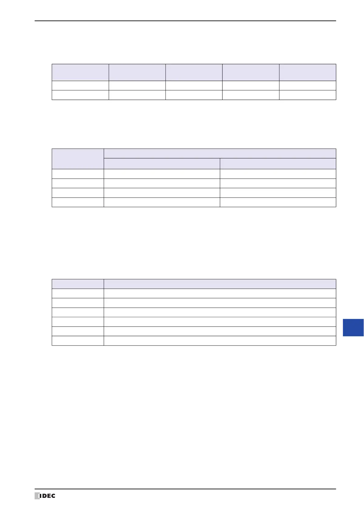
■ Data Type
The analog output value can be handled as the set data type. There are two data types for the analog outputs.
YES: Supported, NO: Not supported
■ Min., Max.
The value written to the data register is output from the analog output. The values of Min. and Max. that can be
written are determined by the set Signal Type and Data Type. A parameter setting error occurs when a value is set
that exceeds the value of Min. or Max. .
The minimum and maximum values that correspond to the signal types and data types are as follows.
■ Data
The analog output data for the analog output set with the Signal Type, the Data Type, the Min. and the Max. is
stored in the data registers in the END progressing of each scan. The actual analog output data is not guaranteed
when the analog output Status is a value other than "0". However, 0V is output when Signal Type is set to -10 to
+10V DC.
■ Status
The status of the analog output Data is stored in data registers.
*1 Min. and Max. can be set only when Data Type is set to Optional range. Set the values of Min. and Max. between -
32,768 and 32,767.
Data Type
FC6A-K2A1
FC6A-K2A4
FC6A-K4A1
FC6A-K4A4
FC6A-L06A1
FC6A-L06A4
FC6A-L03CN1
FC6A-L03CN4
Binary data YES YES YES YES
Optional range YES YES YES YES
Signal Type
Data Type
Binary data
Optional range
*1
0 to 10V DC 0 to 4,095 -32,768 to 32,767
-10 to +10V DC -2,048 to 2,047 -32,768 to 32,767
0 to 20mA DC 0 to 4,095 -32,768 to 32,767
4 to 20mA DC 0 to 4,095 -32,768 to 32,767
Status Description
0 Operating normally
1 Reserved
2 Initializing
3 Parameter setting error
4 Hardware fault (external power supply error)
5 to 65,535 Reserved
 Loading...