5 HG1P
35-72 WindO/I-NV4 User’s Manual
5.4
External Interfaces
CAUTION
• Make sure to turn off the power to the HG1P before inserting or pulling the cable into or out of the
connector.
• Communication interface specifications vary based on the model number.
Communication Interface Specifications
HG1P-ST32YBFH-B0 : Serial Interface (RS422/485)
HG1P-ST32ZBFH-B0 : Ethernet Interface
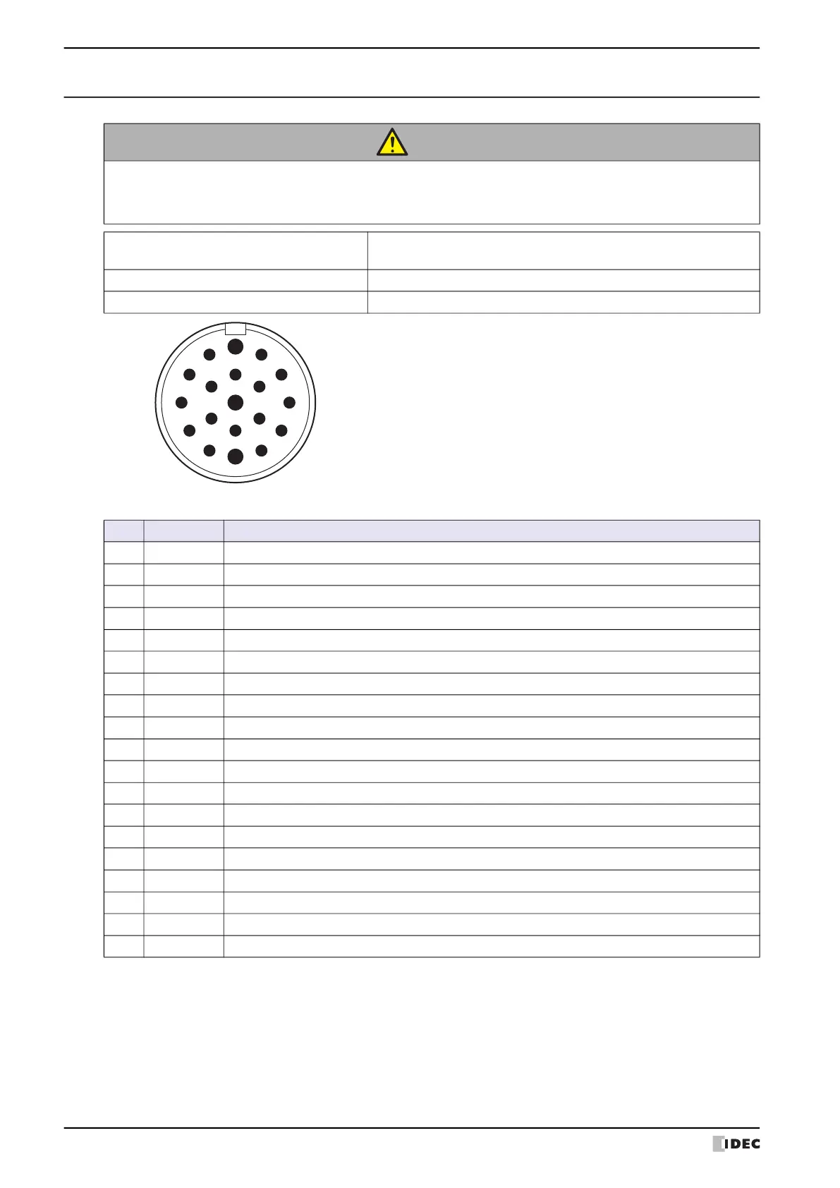
Connector Removable 19-pin Female Connector
Part Number (Manufacturer) CA-19P1N126Y00 (PHOENIX CONTACT)
No. Name Function
1 C_NC1 Selector Switch Contact 1 (NC)
2 C_NO1 Selector Switch Contact 1 (NO)
3 B_C1 Enabling Switch Contact 1 (COM)
4 B_C2 Enabling Switch Contact 2 (COM)
5 B_NO2 Enabling Switch Contact 2 (NO)
6 FG Frame Ground
7 RDA+/TP1+ Receive Data (+)
8 RDB-/TP1- Receive Data (-)
9 SDB-/TP0- Send Data (-)
10 A_NC21 Emergency Stop Switch Contact 2 (NC)
11 A_NC22 Emergency Stop Switch Contact 2 (NC)
12 DC24V- HG1P 24V DC Power Supply (-)
13 C_C1 Selector Switch Contact 1 (COM)
14 B_NO1 Enabling Switch Contact 1 (NO)
15 SG Communication Signal Ground
16 SDA+/TP0+ Send Data (+)
17 A_NC11 Emergency Stop Switch Contact 1 (NC)
18 A_NC12 Emergency Stop Switch Contact 1 (NC)
19 DC24V+ HG1P 24V DC Power Supply (+)
View of mating surface of the removable connector
1
2
3
4
5
6
7
8
9
10
11
12
13
14
15
16
17
18
19
 Loading...