3 Project Settings Dialog Box
4-32 WindO/I-NV4 User’s Manual
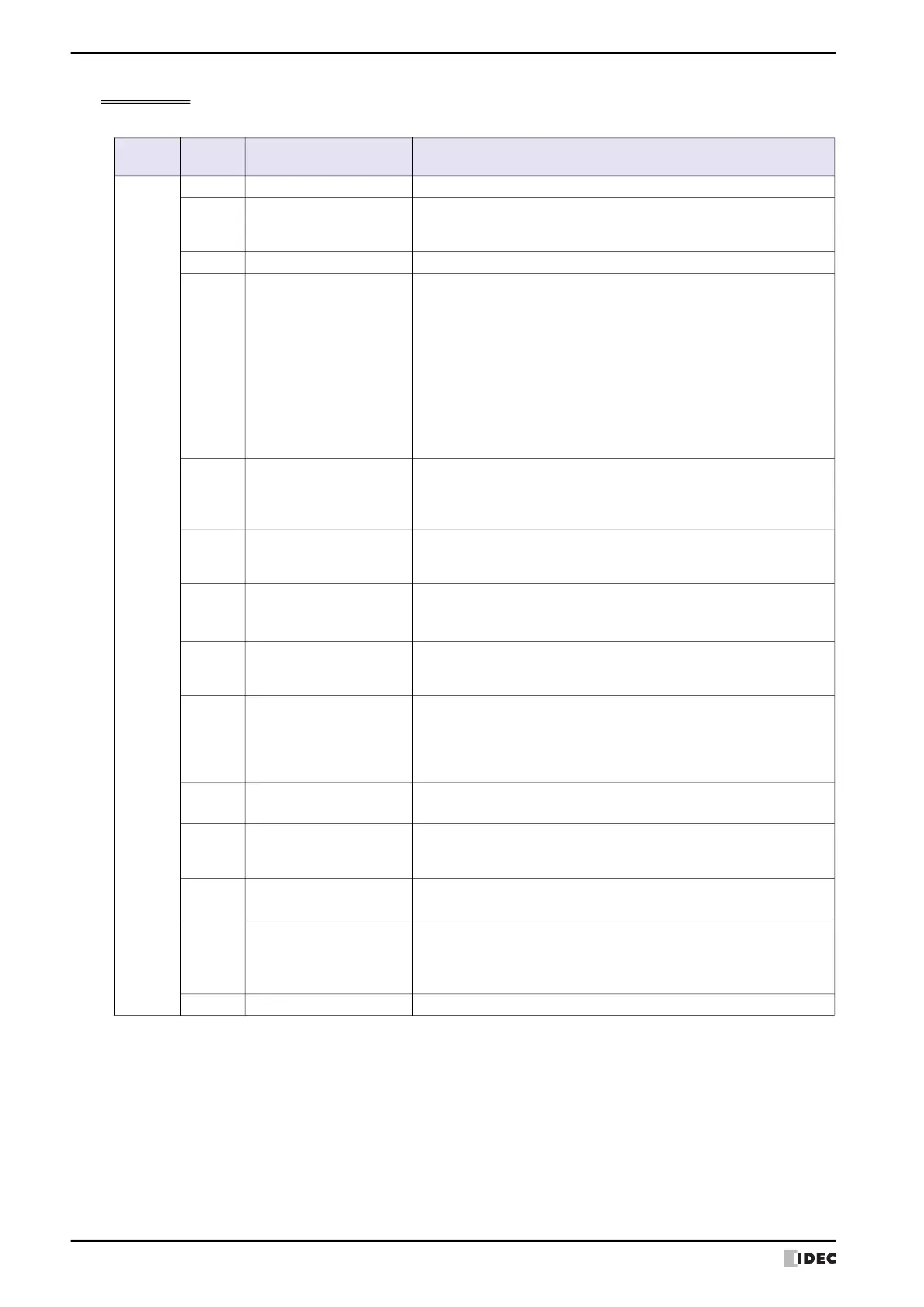
System Area 2
This area stores MICRO/I states and error information. These bits are 0 immediately after the power is turned on.
*1 HG5G/4G/3G/2G-V, HG4G/3G, HG2G-5F only
*2 USB flash drive inserted in USB1 for HG2J-7U, SD memory card for HG5G/4G/3G-V, HG4G/3G and HG2G-5F
*3 HG2G-5T, HG1G/1P only
*4 HG5G/4G/3G/2G-V, HG4G/3G, HG2G-5F/-5T, HG1G only
*5 HG2J-7U, HG5G/4G/3G/2G-V, HG4G/3G, HG2G-5F/-5T, HG1G only
*6 Only clock data is lost for HG2J-7U.
Address
number
Bit Function
Description
+2
0 to 2 Reserved
3 Communication error
This bit changes to 1 when a communication error occurs in external
device communication. To clear this bit, write 1 to the Clear error bit
(System Area 1 address number+1, bit 9).
4 Reserved
5 Processing error
This bit changes to 1 when executing the following arithmetic operations.
To clear this bit, write 1 to the Clear error bit (System Area 1 address
number+1, bit 9).
• There is data which cannot be handled with the specified data type;
BCD4(B), BCD8(EB), or Float32(E).
• A value is divided by 0.
• The setting of Origin, Minimum, or Maximum for the Bar Chart or Line
Chart are invalid, or the Minimum and Maximum are the same values.
• The setting of Minimum, Maximum, or ranges for the Meter are invalid,
or the Minimum and Maximum are the same values.
• There is invalid clock data which is used in Calendar parts.
6 Device range error
This bit changes to 1 when writing a value to a device address that falls
outside its range or when exceeding the restrictions on the number of
configured device addresses. To clear this bit, write 1 to the Clear error bit
(System Area 1 address number+1, bit 9).
7
Clock IC error
*1
This bit changes to 1 when the MICRO/I internal clock stops. To clear this
bit, write 1 to the Clear error bit (System Area 1 address number+1, bit
9).
8
External memory device
(A:) access error
This bit changes to 1 when an error occurs when the external memory
*2
device inserted in the MICRO/I is accessed. To clear this bit, write 1 to the
Clear error bit (System Area 1 address number+1, bit 9).
9
Printer timeout error
*1
This bit changes to 1 when a printing error occurs when data is output to
the printer connected to the MICRO/I. To clear this bit, write 1 to the
Clear error bit (System Area 1 address number+1, bit 9).
10 Script error
This bit changes to 1 when an error occurs during script execution. Error
details are stored in HMI Special Data Registers LSD52 and LSD53. For
details, refer to Chapter 20 “1.4 Script Error” on page 20-4. To clear this
bit, write 1 to the Clear error bit (System Area 1 address number+1, bit
9).
11
External memory device
(B:) access error
*3
This bit changes to 1 when an error occurs when accessing an inserted
USB flash drive.
12
Replace battery error
*4
This bit changes to 1 when it is time to replace the backup battery. To
clear this bit, write 1 to the Clear error bit (System Area 1 address
number+1, bit 9).
13
Replace battery error (low
battery)
*4
This bit changes to 1 when the backup battery is low. To clear this bit,
write 1 to the Clear error bit (System Area 1 address number+1, bit 9).
14
Backup data error
*5
This bit changes to 1 when the data sampled by the log functions, the
clock data and values in the HMI Keep Registers and HMI Keep Relays
disappears
*6
. To clear this bit, write 1 to the Clear error bit (System Area
1 address number+1, bit 9).
15 Reserved
 Loading...