WindO/I-NV4 User’s Manual 8-43
3 Goto Screen Button
8
Buttons
■ Goto Screen
■ View Switching Method
*2
Select how to display the ON/OFF status of the button.
*1 This is applicable for models with a video interface only.
*2 Advanced mode only
Screen Number: If Action Mode is set to Switch to Base Screen, specify the Base Screen number to switch to
(from 1 to 3000). If Action Mode is set to Open Popup Screen or Close Popup Screen,
specify the number of the Popup Screen to open or close (from 1 to 3015).
This setting is enabled only if Action Mode is set to Switch to Base Screen, Open Popup
Screen, or Close Popup Screen.
Use Reference Device Address
*2
:
Select this check box and specify a device address to specify
the screen number using the value of the specified device
address.
Click to display the Tag Editor. For the device address
configuration procedure, refer to Chapter 2 “5.1 Device
Address Settings” on page 2-70.
This setting is enabled only if Action Mode is set to Open
Popup Screen or Close Popup Screen.
Coordinates X, Y: Specify the coordinates on the Base Screen for displaying a window.
X and Y specify the upper left corner of the window using the upper left corner of the screen as the
origin.
This setting is enabled only if Action Mode is set to Open Popup Screen, Open Device
Monitor Screen, Open Password Screen, Open Adjust Brightness Screen, or Open File
Screen for Movie Files
*1
.
Use Reference Device Address
*2
:
Select this check box and specify a device address to specify
the coordinates using the value of the specified device
address.
Click to display the Tag Editor. For the
device address configuration procedure, refer to Chapter 2 “5.1
Device Address Settings” on page 2-70.
This setting is enabled only if Action Mode is set to Open
Popup Screen.
Button: Pressing the button changes the drawing object displayed.
Device Address: The drawing objects assigned to the OFF and ON states are displayed when the value of the device
address is 0 and 1, respectively. Specifies the device used to switch the drawing object display.
Click to display the Tag Editor. For the device address configuration procedure, refer to Chapter
2 “5.1 Device Address Settings” on page 2-70.
No Image: The button is not displayed on the screen. The button appears as a dashed line frame on the edit
screen. Pressing the corresponding area on the MICRO/I activates the assigned function. If No
Image is selected, the settings for View and Registration Text are disabled.
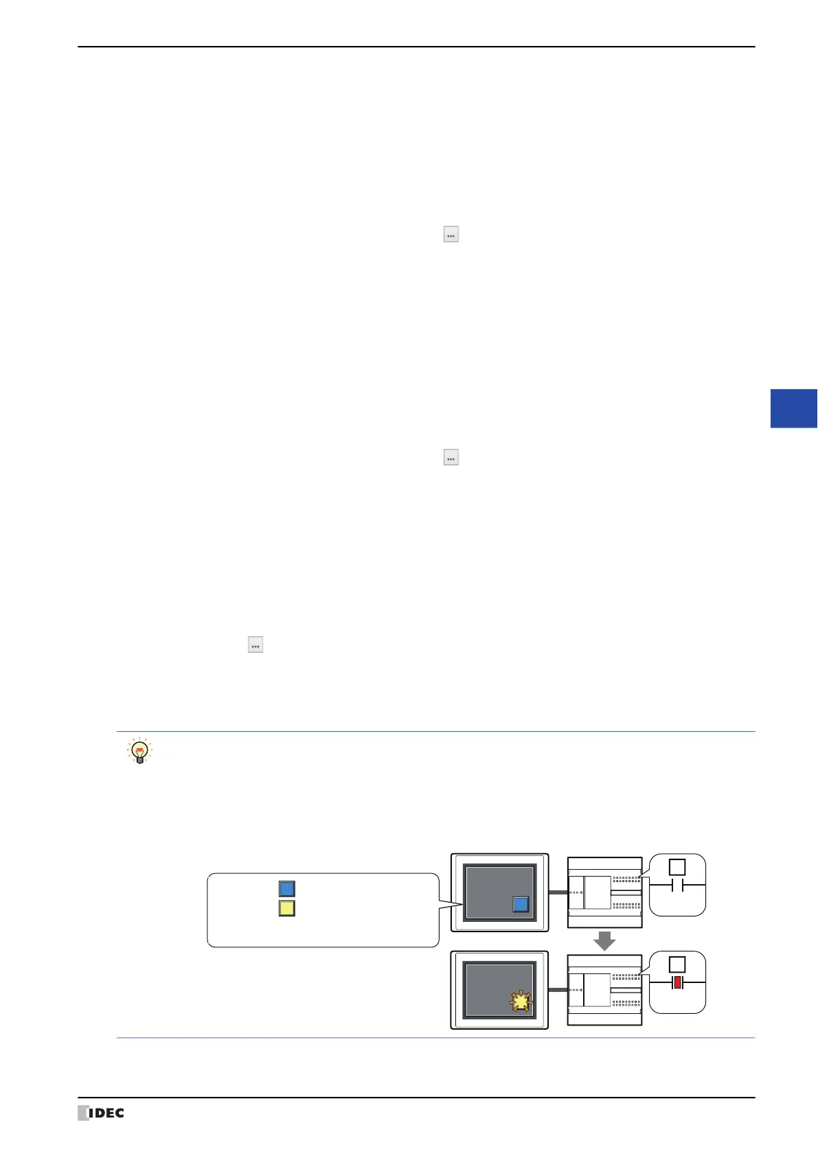
Selecting Device Address in View Switching Method allows you to create an illuminated pushbutton.
The illuminated pushbutton switches state (or image) according to ON or OFF state of the device address,
allowing you to display the state of a device that is being operated.
Example: When you set an external device address 'M0' as Device Address in View Switching Method, if
the value of M0 changes, the display image will switched according to the value of M0 even if the
button is not pressed.
0
M0
1
M0
MICRO/I External device
View Switching Method (Device Address): M0
OFF image:
ON image: