196 Measurement Technique
imc CANSAS Users Manual - Doc. Version 1.9 - 05.12.2014© 2014 imc Meßsysteme GmbH
5.1.3.1.3 Scaling
A maximum value must be entered under Input range (max. frequency etc, depend on mode). This
Maximum determines the scaling factor of the computational processing and amounts to the range
which is represented by the available numerical format of 16bits. Depending on the measurement mode
(quantity to be measured), it is to be declared as an input range's unit or in terms of a corresponding
max. pulse rate.
In the interest of maximizing the measurement resolution it is recommended to set this value
accordingly.
The Scaling is a sensor specification which states the relation between the pulse rate of the sensor and
it's corresponding physical units (sensitivity). This is also the place to enter a conversion factor for the
sensor along with any physical quantity desired, for instance, to translate the revolutions of a flow gauge
to a corresponding volume.
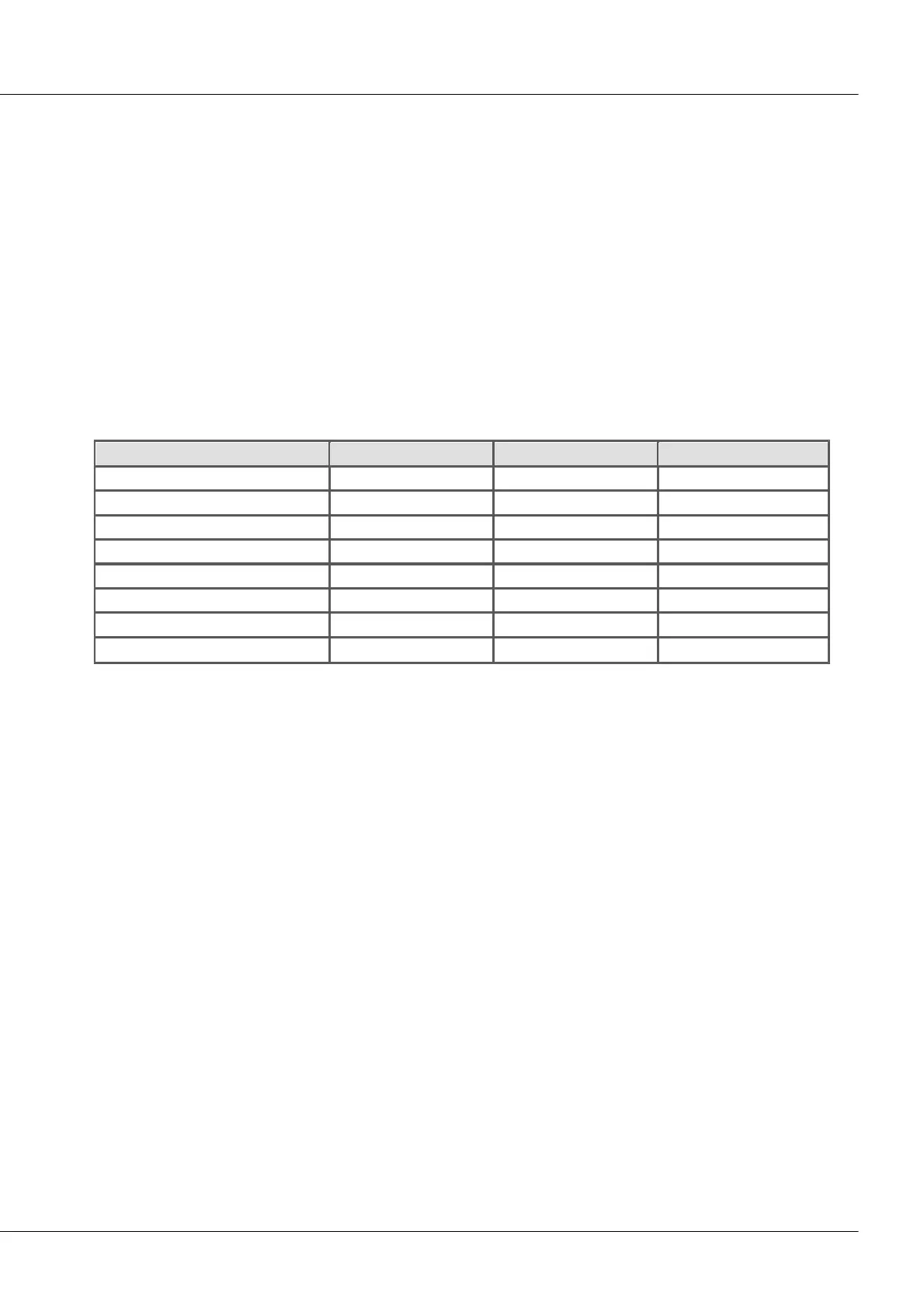
The table below summarizes the various measurement types' units; the bold, cursive letters denote the
(fixed) primary quantity, followed by its (editable) default physical unit:
5.1.3.1.4 Comparator conditioning
The incremental encoders' special properties make special demands for signal quality: the very high
resolution offered by the detector or counter means that even very short impulses can be captured and
evaluated, which sampling-based measurement methods (such as for the digital inputs of the DI16
module) would not (or almost never) be able to detect. Therefore, the digital signals must have clear
edges in order not to produce disturbed readings. Spurious impulses or contact bouncing can lead to
artifacts such as enormous peaks in RPM-signals etc..
Simple sensors working on the principles of induction or photoelectric relays often emit unconditioned
analog signals which must be evaluated according to a threshold condition. Aside from that, problems
can occur even with conditioned encoder signals (e.g. TTL-levels) due to long cables, bad reference
voltages, ground loops or interference. imc incremental encoder channels are able to counteract these
problems thanks to a special 3-stage conditioning unit.
First comes a high-impedance differential amplifier (± 10 V range, 100 kΩ) which enables reliable
acquisition from a sensor even over a long cable as well as effective suppression of common mode
interference and ground loops. Next, a (configurable) smoothing filter offers additional interference
suppression adapted to the measurement situation. Lastly, a comparator with adjustable threshold and
hysteresis serves as a digital detector. The (adjustable) hysteresis also serves to suppress interference.