476 General Technical Specs
imc CANSAS Users Manual - Doc. Version 1.9 - 05.12.2014© 2014 imc Meßsysteme GmbH
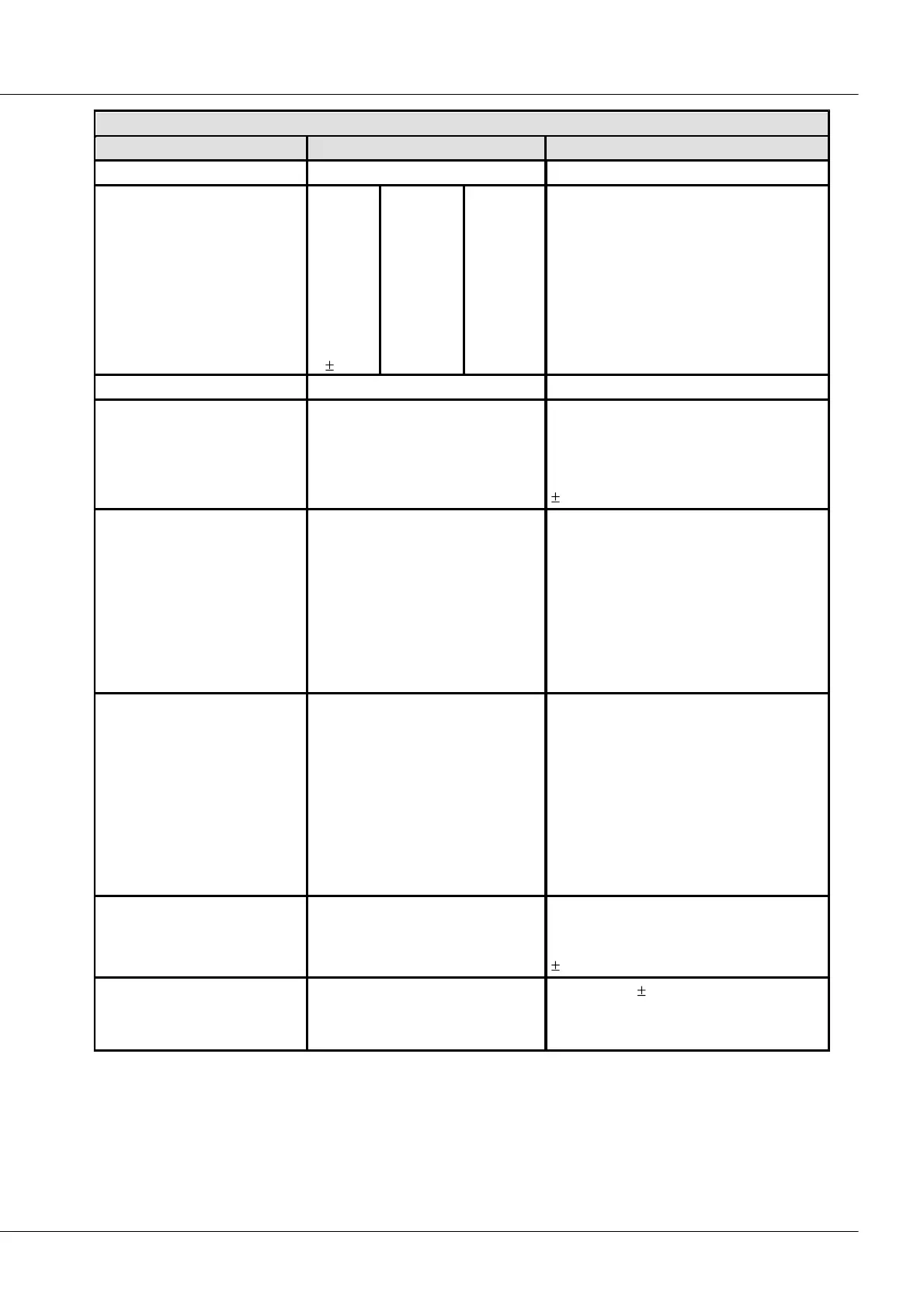
Built-in DCB8 Sensor Supply
Voltage
+2.5 V
+5.0 V
+7.5 V
+10 V
+12 V
+15 V
+24 V
15 V
Current
580 mA
580 mA
400 mA
300 mA
250 mA
200 mA
120 mA
190 mA
Net power
1.5 W
2.9 W
3.0 W
3.0 W
3.0 W
3.0 W
2.9 W
3.0 W
set globally, isolated on request
available on request
1
(only without isolation ; not with LEMO)
to reference ground of the output voltage
Output voltage accuracy
2
<0.25% (typ.)
<0.5% (max.)
<0.9% (max.)
<1% (max.)
at terminal plugs, no load
25°C; 2.5 V to 24 V
25°C; 2.5 V to 24 V
over entire temperature range
2
15 V
Compensation of
cable resistances
measurement mode:
voltage measurement with
adjusted supply
3-wire circuit:
single sense wire:
sensing of return line only
( –VB: supply ground)
physical adjustment of voltage (+VB)
Provided for 5 V.
Prerequisites:
1) symmetrical feed and return lines,
2) identical wires for all channels,
3) representative measurement at
Channel1
Compensation of
cable resistances
measurement mode:
bridge measurement, strain gauge
3-wire circuit:
single sense wire:
sensing of return line only
( –VB: supply ground)
voltage drops dynamically
monitored and numerically
compensated
Provided for 2.5 V, 5 V and 10 V.
Prerequisites:
1) symmetrical feed and return lines
differing cable length for individual
channels allowed
min. 40%
typ. 55%
typ. 50%
typ. 70%
2.5 V
5 V, ..15 V
24 V
15 V
2.5 V, ..10 V, 15 V
12 V, 15 V
24 V
1
With option ±15V the quarter bridge is not supported, because the ¼ bridge pin is used for–15V
Also the ground referenced current measurement no longer applies
2
The precision of the bridge measurement is not affected by actual precision of the bridge supply. The current value of
the bridge supply is continuously monitored and compensated.