560 Pin configuration and power supply
imc CANSAS Users Manual - Doc. Version 1.9 - 05.12.2014© 2014 imc Meßsysteme GmbH
Step 4: Feed the cable through the gland in accordance with the manufacturer’s instructions and con-
nect the leads according to the pin configuration for connector pins .
Step 5: Re-attach the connector junction into its former position by means of the clamping brackets.
Gently tug the cable back outwards through the gland in order to straighten out the individual leads, to
prevent them from possibly becoming bent or stuck. When installing the connector junction, ensure that
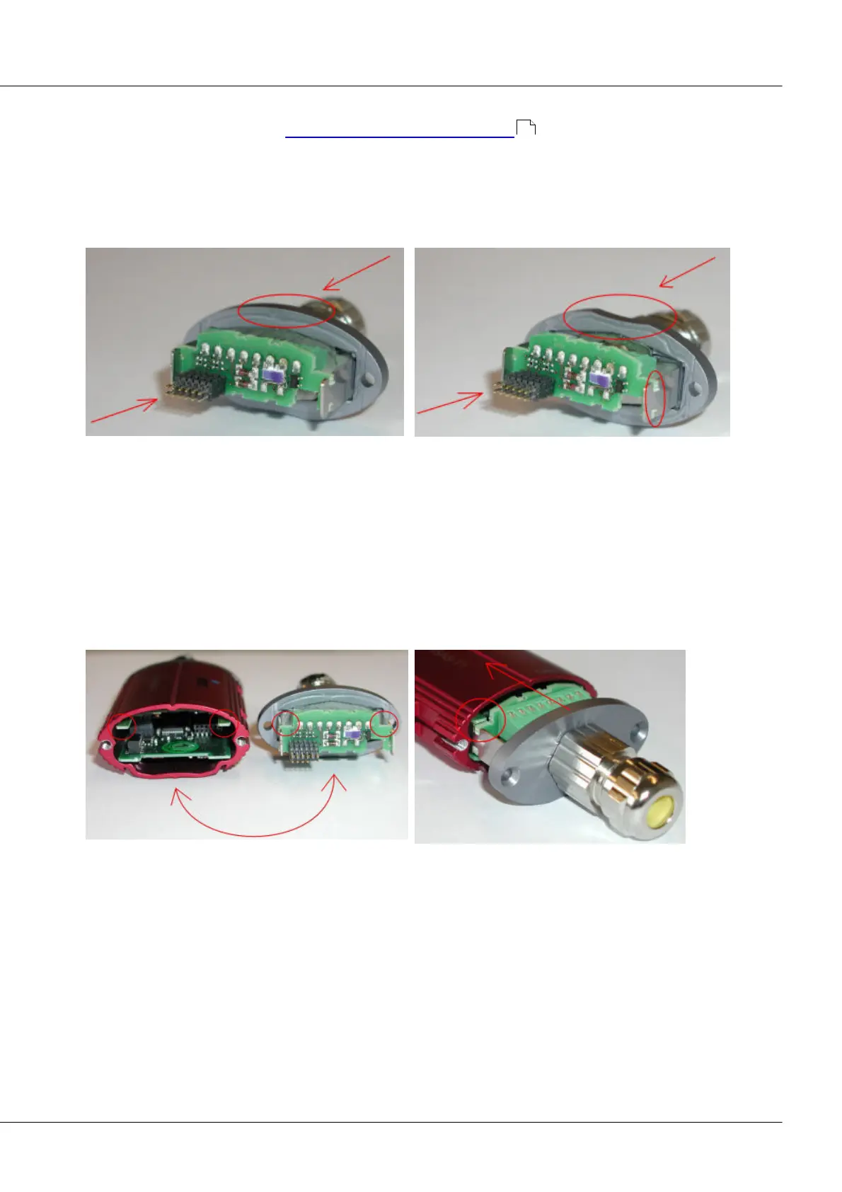
it is not positioned upside down. The recess in the profile of the housing face is an indication of whether
the connector junction is installed correctly.
Correct connection junction position
Incorrect connection junction position
Step 6: Check that the cable and leads are not under strain or tension and then close the cable gland,
which is designed for cables of 4 – 6 mm in diameter. If the cable used is thinner, then its diameter in the
section passing through the gland must be made correspondingly wider by means of heat-shrinkable
tubing.
Step 7: Carefully insert the housing face into the housing. Make absolute certain that the housing and its
face are attached together in the correct position. This can be ascertained on the basis of the grooves in
the connector junction's plate which are shaped to accommodate the guide rails inside the housing (see
photos below). Also, the correct position is distinguished by the recess in the profile of the housing face,
which fits over one side of the housing.
Step 8: Once the housing face is placed flush on the housing, the module can be closed tight with the
Torx screws.
558