Repair information 4-87
7510
Upper printer engine card bracket assembly removal
1. Remove the rear cover assembly. See “Rear cover assembly removal” on page 4-5.
2. Remove the right cover assembly. See “Right cover assembly removal” on page 4-4
3. Remove the top cover assembly. See “Top cover assembly removal” on page 4-4.
4. Remove the RIP card assembly. See “RIP card assembly removal” on page 4-84.
5. Remove the controller box top cover assembly. See “RIP card cooling fan cover assembly removal” on
page 4-80.
6. Remove the switch (main power). See “Switch (main power) removal” on page 4-82.
7. Remove the controller box assembly. See “Controller box assembly removal” on page 4-81.
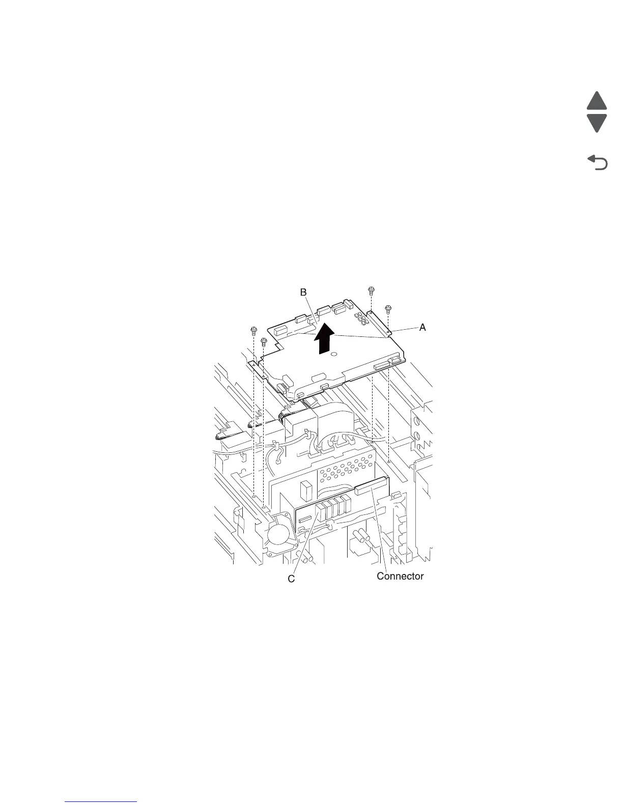
8. Disconnect the thirteen connectors from the upper printer engine card assembly (A).
9. Release the harnesses from the clamps.
10. Remove the four screws securing the upper printer engine card bracket assembly (A) to the machine.
Note: When removing the upper printer engine card bracket assembly (A), the upper printer engine card
assembly (B) and the lower printer engine card assembly (C) will become detached.
11. Lift the upper printer engine card bracket assembly (A).
12. Remove the upper printer engine card bracket assembly (A).
 Loading...