4-36 Service Manual
7510
Printer left door assembly removal
1. Remove the rear cover assembly. See “Rear cover assembly removal” on page 4-5.
2. Remove the rear left middle cover. See “Rear left middle cover removal” on page 4-6.
3. Remove the MPF feed unit assembly. See “MPF feed unit assembly removal” on page 4-8.
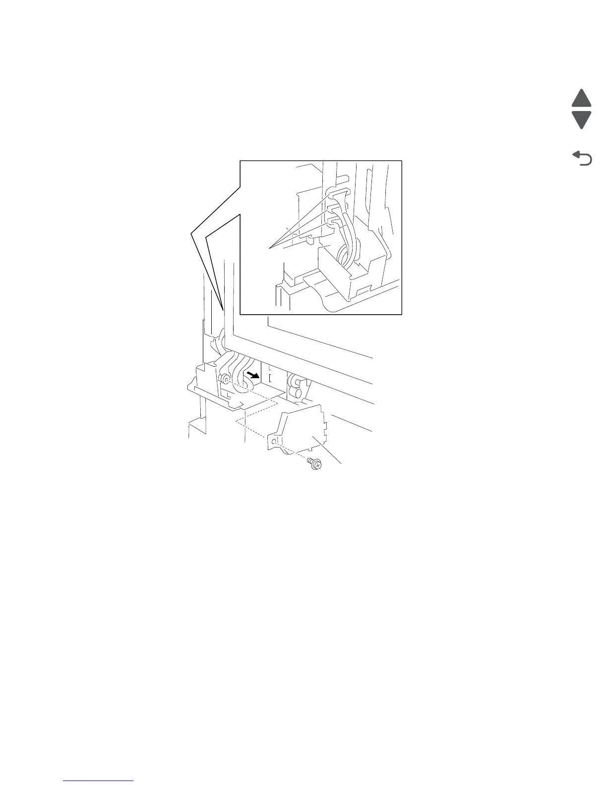
4. Remove the screw securing the connector access cover (A) to the machine.
5. Remove the connector access cover (A).
6. Disconnect the three connectors from the printer left door assembly (B).
7. Gently pull the harnesses through the hole in the machine frame.
8. Open the printer left door assembly (B).
9. Remove the front left cover. See “Front left cover removal” on page 4-9.
10. Remove the safety screw from the machine.
11. Detach the safety arm (C) from the machine.
12. Remove the C-clip from the machine.
13. Remove the support arm (D) from the machine.
14. Lower the printer left door assembly (B) to an approximate 75° angle as shown in the graphic.
15. Lift the printer left door assembly (B) up to remove it from the machine.
16. Remove the printer left door assembly (B).
 Loading...