4-94 Service Manual
7510
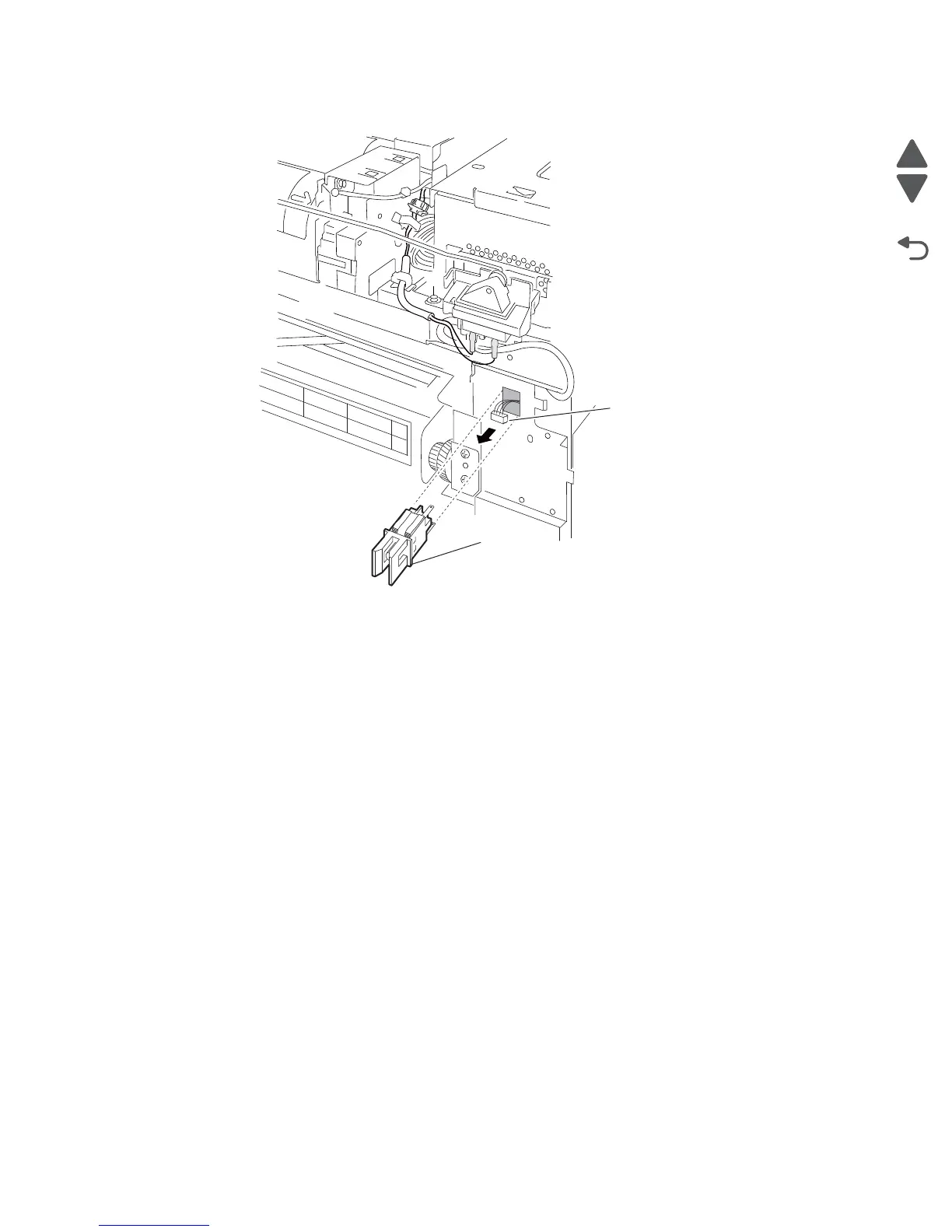
7. Remove the switch (transfer belt access door interlock) (A).
Laser diode power card assembly removal
1. Remove the rear cover assembly. See “Rear cover assembly removal” on page 4-5.
2. Remove the rear upper cooling fan bracket assembly. See “Rear upper cooling fan bracket assembly
removal” on page 4-111.
3. Remove the developer / transfer roll HVPS card assembly. See “Developer / transfer roll HVPS card
assembly removal” on page 4-112.
4. Remove the lower printer engine card bracket assembly. See “Lower printer engine card bracket
assembly removal” on page 4-90.
5. Disconnect the connector from the laser diode power card assembly (A).
6. Release the four plastic supports with needle nose pliers.
 Loading...