4-274 Service Manual
7510
5
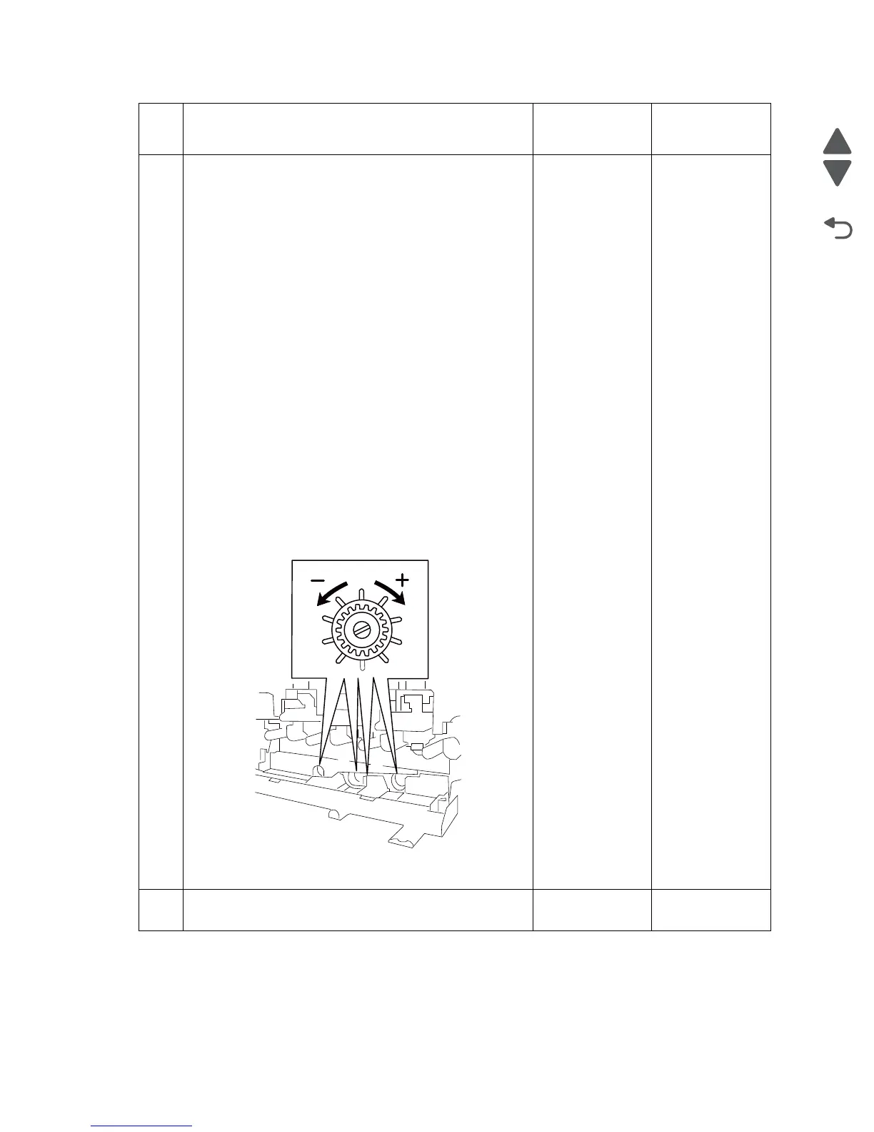
Perform the In/out skew setup printhead adjustment.
1. Enter the Diagnostics Menu.
2. Touch ENGINE ADJUST.
3. Touch RegCon adjust
4. Touch Control setup cycles
5. Touch Cycle result values
Locate the following new values for the following settings:
Y- Skew adjustment
M- Skew adjustment
C- Skew adjustment
K- Skew adjustment
Turn the appropriate printhead adjustment screws, located
behind the waste toner cartridge, the number of clicks
(rotation until a snap sound is heard and felt) based on the
above settings.
+values require turning the screw Clockwise
- values require turning the screw Counter Clockwise.
EG: Y-Skew adjustment 10. Turn the screw CW 10 clicks.
EG: Y-Skew adjustment -10. Turn the screw CCW 10 clicks.
Have the appropriate printhead adjustment screw been
adjusted?
Go to the Center
setup.
See “Center
setup” on
page 4-276.
Adjust the
printhead
adjustment screw
then go to Center
setup.
See “Center
setup” on
page 4-276.
6
Check the image density sensor assembly connection.
Is the above component properly connected
Go to step 7. Replace the
connection.
Step Check Yes No
K
C
M
Y
Printhead adjusting screw
 Loading...