2.45
Date Code 20170927 Instruction Manual SEL-751 Relay
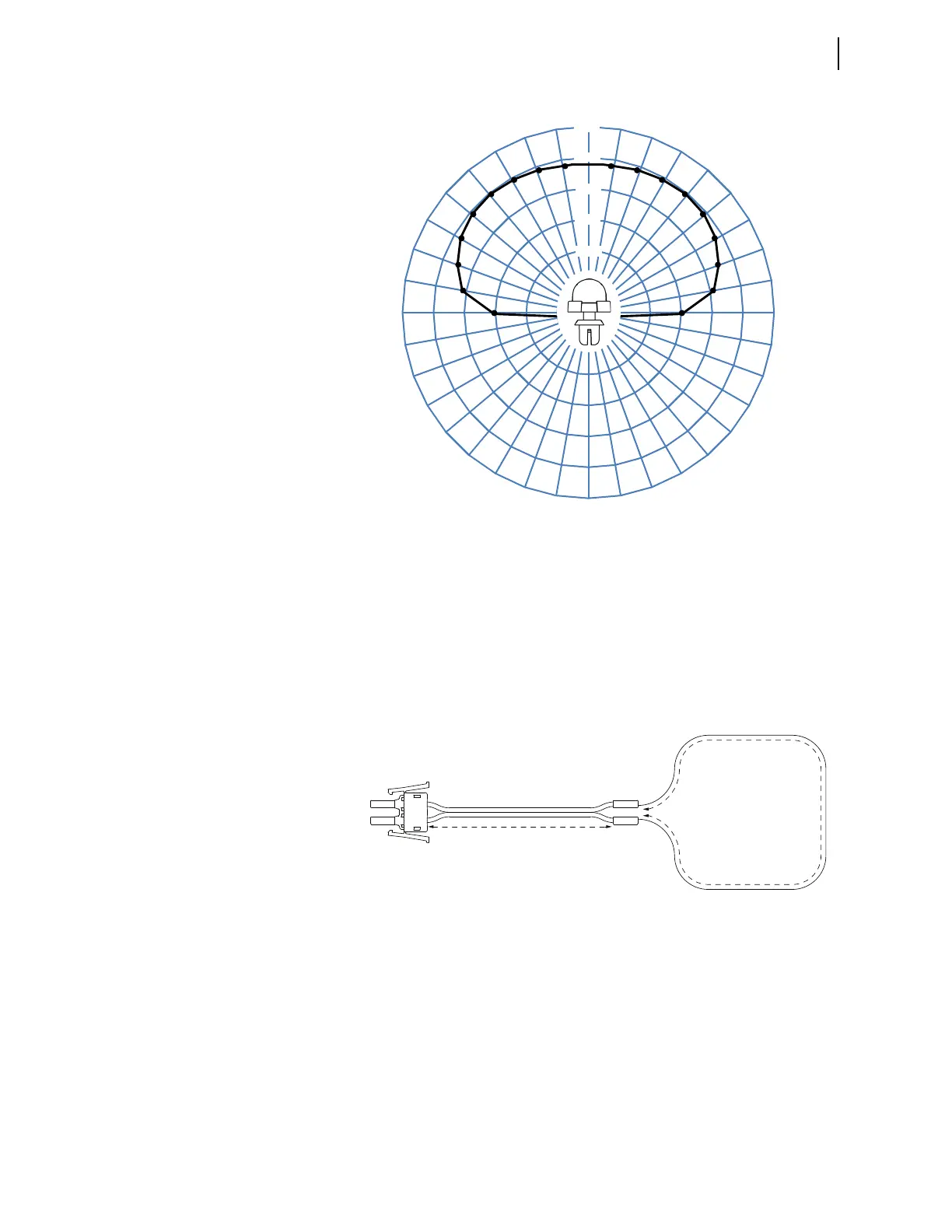
Installation
Arc-Flash Protection: System Installation
Figure 2.39 Point-Sensor Directivity (Left to Right, Above the Mounting
Plane)
Fiber Sensor
Installation
The clear-jacketed fiber sensor is optimized for monitoring of large distrib-
uted resources, such as switchgear system bus enclosures. The clear-jacketed
fiber sensor is omnidirectional and can be mounted in close proximity to the
switchgear enclosure walls. Figure 2.40 shows a schematic diagram of the
clear-jacketed fiber sensor. Figure 2.41 shows a clear-jacketed fiber sensor
mounting example photo.
Total loop length = 2 • A + B (allowed range 3 to 70 meters)
Range for A: 1 to 30 meters
Range for B: 1 to 50 meters
Figure 2.40 Clear-Jacketed Fiber Sensor Assembly
120%
100%
80%
60%
40%
0°
350° 10°
340° 20°
330° 30°
320° 40°
310° 50°
300° 60°
290° 70°
280° 80°
270° 90°
260° 100°
250° 110°
240° 120°
230° 130°
220° 140°
210° 150°
200° 160°
190° 170°
180°
i8004c
Dual V-Pin
Latch
V-Pin
Terminators
V-Pin or
ST Splice
Connector
“A” Meters
“B” Meters
Clear-Jacketed Fiber
Black-Jacketed Fiber Zipcord Duplex