4.94
SEL-751 Relay Instruction Manual Date Code 20170927
Protection and Logic Functions
Group Settings (SET Command)
Thermal Element Logic
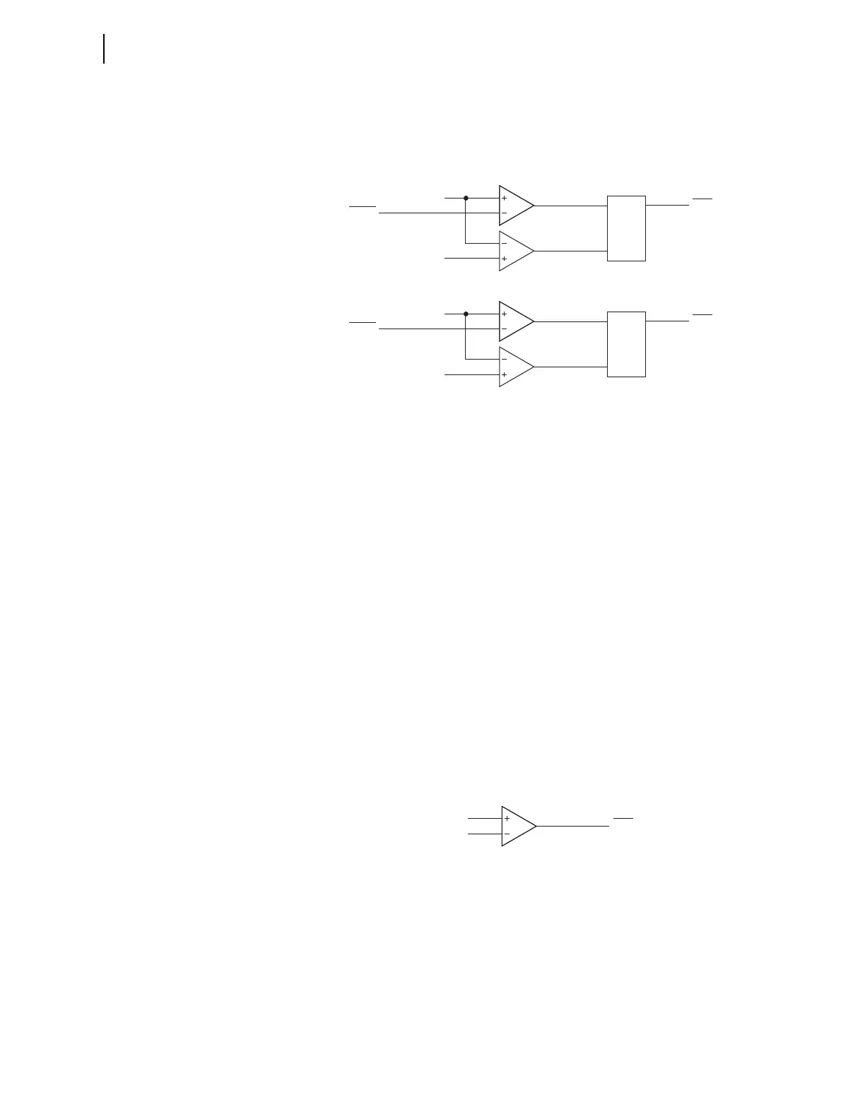
Figure 4.59 shows the thermal alarming and tripping logic for each of the
three thermal elements (n = 1, 2, or 3).
n = 1, 2, or 3.
Figure 4.59 Thermal Alarm and Trip Logic
When considering settings levels for the thermal elements alarming and trip-
ping functions, note from Equation 4.5 that the relay calculates the steady
state thermal level as shown in Equation 4.13:
Equation 4.13
From this equation, the per-unit thermal level that the relay computes depends
on the per unit current flowing through the equipment (THIEQ), and the
KCONS and IBAS settings. These make up the IMC value and the ambient
temperature factor, FAMB. Given this information, you can set the thermal
level alarm and trip thresholds when considering the various operating current
levels and temperatures that the equipment may be subjected to.
The relay makes the three calculated thermal levels THRLn available as
analog quantities. Additionally, the three thermal level alarming Relay Word
bits, THRLAn, as well as the three thermal level tripping Relay Word bits,
THRLTn, are available.
Figure 4.60 shows the logic for thermal element current overload.
n = 1, 2, or 3.
Figure 4.60 Thermal Element Current Overload Logic
Thermal Element Settings
See Table 4.33 for a list of the prompt, ranges, and default settings for the fol-
lowing thermal element settings. The enable IEC thermal element (E49IEC)
setting enables 1, 2, or 3 independent thermal elements.
S
R
Q
THRLn
*
100
THLAn
THLADRn
*
THLAn
Setting
THRLAn
S
R
Q
THRLn
*
100
THLTn
THLTDRn
*
THLTn
Setting
THRLTn
Relay
Word
Bit
Relay
Word
Bit
THRL
SS
THIEQ
IMC
-------------------
2
FAMB=
THOVLn
t
IMCn
Relay
Word
Bit
THIEQn
t