9.16
SEL-751 Relay Instruction Manual Date Code 20170927
Bay Control
Bay Control Application Example
Table 9.6 lists the number of each symbol required to draw the single-line
diagram shown in Figure 9.10.
Edit Symbol Properties
All of the symbols in Bay Screen Builder include editable properties. These
properties allow you to customize the symbols to your specific application.
These properties appear in the right Properties pane of Bay Screen Builder
either when you drag a symbol from the left Symbols pane and drop it in the
screen area or when a symbol in the screen area is selected.
For example, you can use the Close/Open/Alarm Color property in the
Appearance tab of the breaker properties to select a color scheme for your
single-line diagram breaker.
Step 1. Select the existing breaker symbol in the predefined single-line
diagram to display the breaker symbol properties in the
Properties pane, as shown in Figure 9.15.
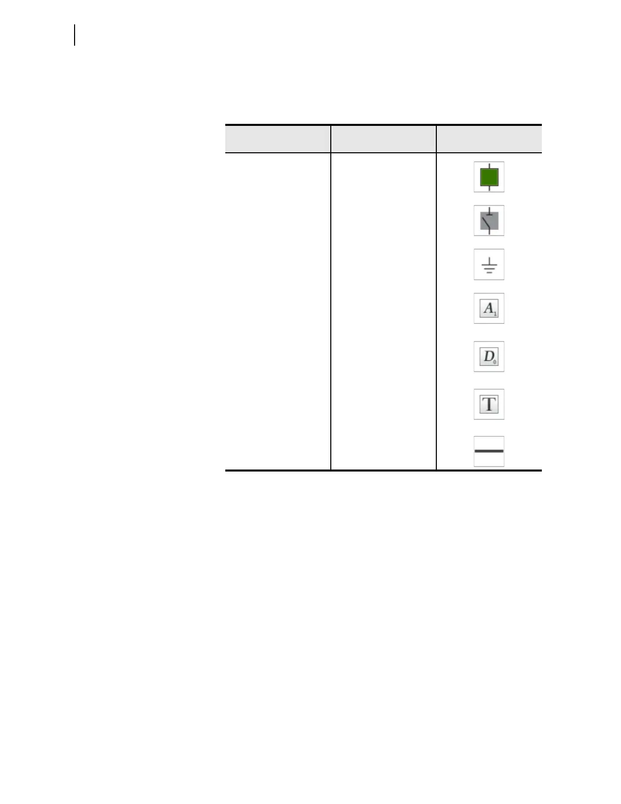
Table 9.6 Symbols Required for the Single-Line Diagram Schematic in
Figure 9.10
Symbols Required
Number of Symbols
Required
Symbol
Breaker
1
Disconnect switches
3
Ground
1
Analog labels
(display voltages, currents,
and power)
8
Digital label
(display breaker SF6 gas
pressure OK or LOW)
1
Text boxes
(identify the relay, feeder
name, nominal bus voltage)
3
Line
(draw the bus
and connections)
As Needed