9.17
Date Code 20170927 Instruction Manual SEL-751 Relay
Bay Control
Bay Control Application Example
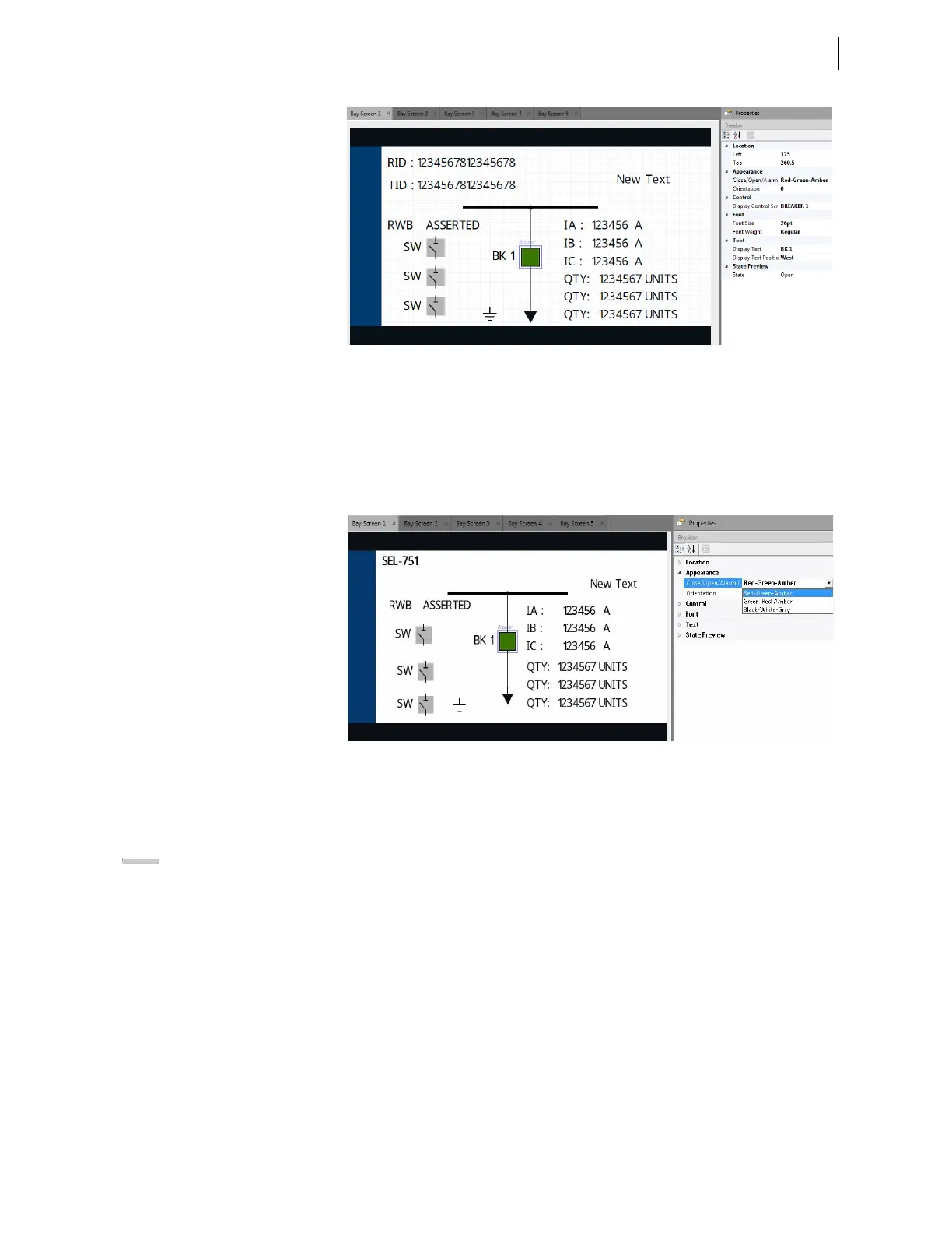
Figure 9.15 Selected Breaker Symbol Settings Displayed in the Properties
Pane
Step 2. Select a color option from the drop down menu to edit the
Close/Open/Alarm Color property in the Appearance tab
(see Figure 9.16).
Table 9.1 lists the available options and breaker appearance in
each state based on the selected property.
Figure 9.16 Close/Open/Alarm Color Property Drop Down Menu
Step 3. Use the State Preview tab to view your breaker close, open,
and alarm state color selections.
Step 4. Edit the additional properties as needed for your application.
Select and edit the disconnect switches, dynamic labels (analog and digital
labels), and static symbols, similar to the breaker symbol. Note that some of
the symbols have the Text tab that can be edited for custom labeling.
In this example, only Bay Screen 1 has been modified in the project. You can
also modify the other screens to add analog/digital labels to monitor the status
of the quantities, if necessary. Publish the project using the following process
after saving your edits.
NOTE: The assignment of breaker
Relay Word bits (e.g., 52A, 52B) to
breaker symbols, or analog
quantities (e.g., VA_MAG) to analog
labels, cannot be made in Bay Screen
Builder. These assignments can only
be made in QuickSet.