11.2
SEL-751 Relay Instruction Manual Date Code 20170927
Testing and Troubleshooting
Testin g Tools
Low-Level Test
Interface
The SEL-751 has a low-level test interface on the 4 ACI/3 AVI current/voltage
card with both the LEA voltage inputs and the regular voltage inputs in Slot Z
and on the 2 AVI/4 AFDI voltage card with both the LEA voltage input and
the regular voltage input for the VS channel in Slot E. You can test the relay in
either of two ways: conventionally, by applying ac signals to the relay inputs
or by applying low magnitude ac voltage signals to the test interface on the
printed circuit boards.
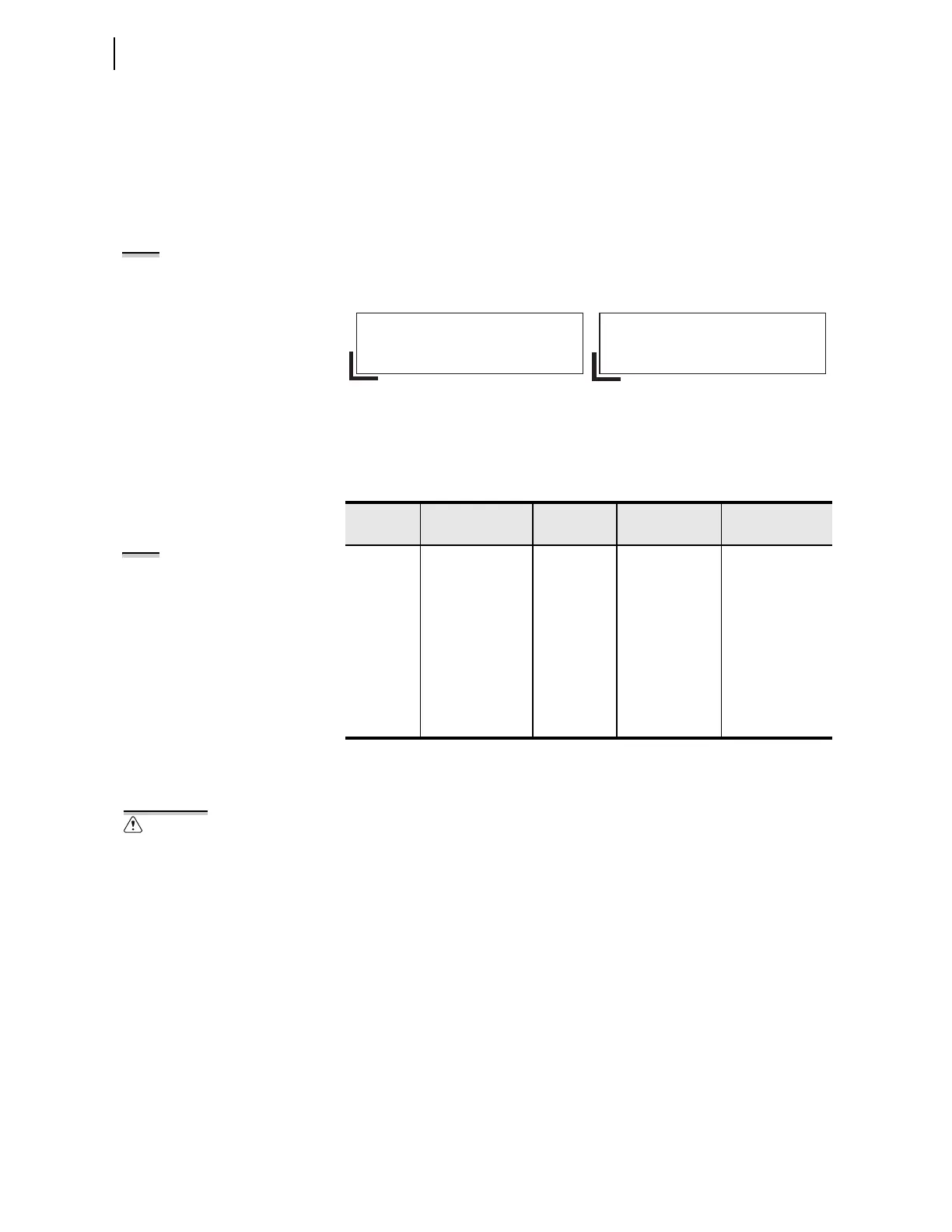
You can use the SEL-RTS Low-Level Relay Test System to provide signals to
test the relay. Figure 11.1 shows the Test Interface connectors.
Figure 11.1 Low-Level Test Interface (J2 and J4)
Table 11.1 shows the signal scale factor information used by the AMS Relay
Test System SEL-5401 Software for the calibrated inputs.
Access the low-level test interface connectors by using the following procedure.
Make sure to turn off the relay at the start of Step 1. Turn the relay back on
after Step 9. Refer to the SEL-RTS Instruction Manual for additional detail.
Step 1. Remove the control voltage and ac signals from the SEL-751
by opening the appropriate breaker(s) or removing fuses.
Step 2. Loosen the mounting screws and the ground screw on the back
and remove the back cover.
Step 3. Remove the 4 ACI/3 AVI board from Slot Z.
Step 4. Locate connector J3 and change four jumpers from Pin CT
(normal position) to Pin AMS (low-level test position).
Step 5. Locate connector J2, remove four current jumpers (IA, IB, IC,
and IN), and connect low-level signal connector (e.g., ribbon
cable connector of SEL-RTS Test System).
Step 6. Insert the 4 ACI/3 AVI board back in its Slot Z.
Step 7. Remove the 2 AVI/4 AFDI board from Slot E.
Table 11.1 Resultant Scale Factors for Inputs
Channel
Label
Circuit Board &
Connector
SEL-5401
Channel No.
Nominal Input
Scale Factor
a
(A/V or V/V)
a
Scale Factors for LEA voltage inputs are same as regular PT inputs.
IA J2 on Slot Z card 1 5 A/1 A 106.14/21.23
IB J2 on Slot Z card 2 5 A/1 A 106.14/21.23
IC J2 on Slot Z card 3 5 A/1 A 106.14/21.23
VA J2 on Slot Z card 4 300 V/8 V LEA 218.4/5.84
VB J2 on Slot Z card 5 300 V/8 V LEA 218.4/5.84
VC J2 on Slot Z card 6 300 V/8 V LEA 218.4/5.84
IN J2 on Slot Z card 7 5 A/1 A/0.2 A 106.14/21.23/6.86
VS J4 on Slot E card 8 300 V/8 V LEA 218.4/5.84
NOTE: The SEL-RTS Relay Test
System consists of the SEL-AMS
Adaptive Multichannel Source and
SEL-5401 Test System Software.
GND GND GND GND GND GND GND
ooooooo
ooooooo
IA IB IC VA VB VC IN
4 ACI/3 AVI Card
GND
ooooooo
ooooooo
VS
2 AVI/4 AFDI Card
Connector J2 on Slot Z Card Connector J4 on Slot E Card
975311113
8642101214
975311113
8642101214
NOTE: If you use a 4 ACI card in
Slot Z, the voltage channels do not
apply.
Equipment components are sensitive
to electrostatic discharge (ESD).
Undetectable permanent damage can
result if you do not use proper ESD
procedures. Ground yourself, your
work surface, and this equipment
before removing any cover from this
equipment. If your facility is not
equipped to work with these
components, contact SEL about
returning this device and related SEL
equipment for service.