4.53
Date Code 20170927 Instruction Manual SEL-751 Relay
Protection and Logic Functions
Group Settings (SET Command)
q From Figure 4.39; w Figure 4.6; e Figure 4.2.
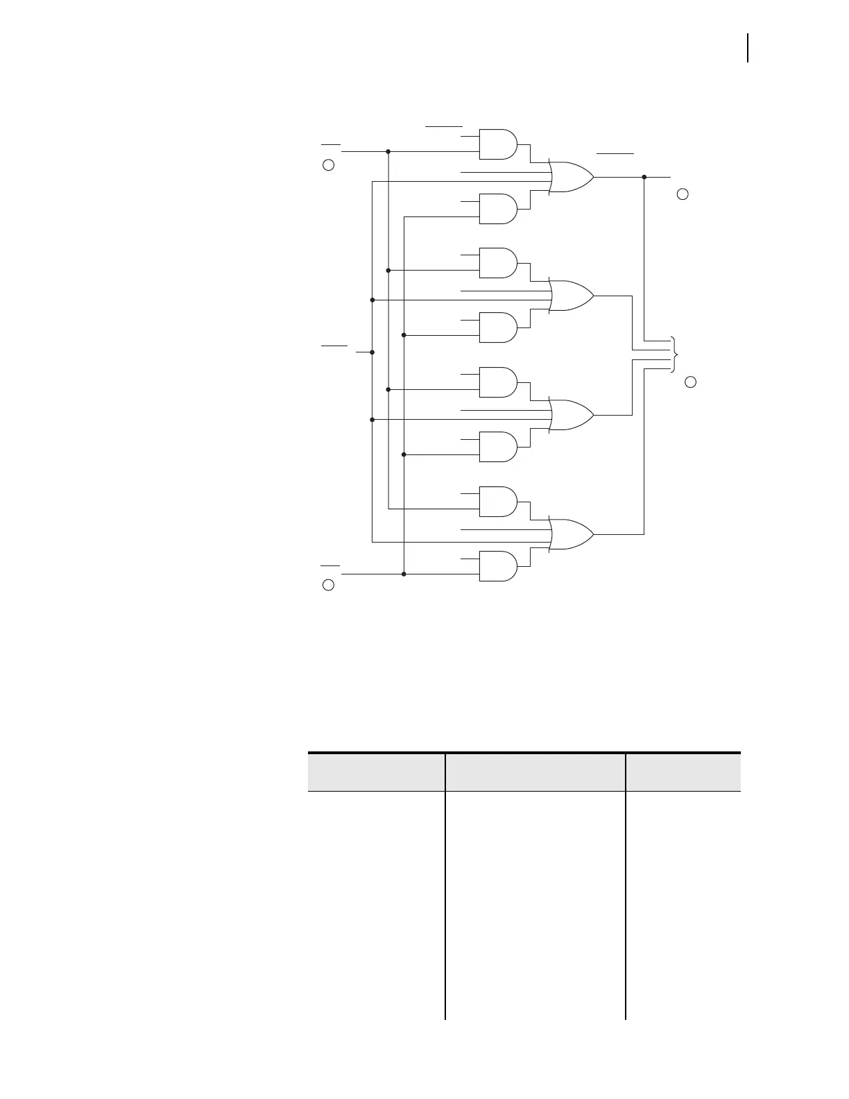
Figure 4.41 Direction Forward/Reverse Logic for Phase Overcurrent
Elements
Directional Control
Settings
Table 4.22 and Ta ble 4.23 show all the directional element settings. The
Wattmetric element settings for Petersen coil-grounded systems are shown in
Table 4.23.
Level
Direction
Settings
DIRPF
DIR1 = F
DIR1 = N
Relay
Word
Bit
Relay
Word
Bit
to Phase
Time-0vercurrent
Elements
to Phase
Instantaneous/
Definite-Time
Overcurrent
Elements
VNOM = OFF
Setting
Forward
Forward
DIRPR
Reverse
DIR1 = R
Reverse
DIR2 = F
DIR2 = N
Forward
DIR2 = R
Reverse
DIR3 = F
DIR3 = N
Forward
DIR3 = R
Reverse
DIR4 = F
DIR4 = N
Forward
DIR4 = R
Reverse
1
1
2
3
Directional
Control
Level 1
P1DIR
Level 2
P2DIR
Level 3
P3DIR
Level 4
P4DIR
Table 4.22 Directional Control Settings (Sheet 1 of 2)
Setting Prompt Setting Range
Setting Name :=
Factory Default
DIR CONTROL ENBL Y, AUTO, N EDIR := N
FWD DIR ON LOP Y, N EFWDLOP := Y
DIR CONTROL LVL1 F, R, N DIR1 := N
DIR CONTROL LVL2 F, R, N DIR2 := N
DIR CONTROL LVL3 F, R, N DIR3 := N
DIR CONTROL LVL4 F, R, N DIR4 := N
GND DIR PRIORITY Q, V, I, U, S, P, OFF
a
ORDER := OFF
PH DIR 3PH LVL 0.50–10.00 A
b
50PDIRP := 3.00
b
FWD DIR Z2 LVL –128.00 to 128.00 ohm
c
Z2F := –0.06
c
REV DIR Z2 LVL –128.00 to 128.00 ohm
c
Z2R := 0.06
c