4.186
SEL-751 Relay Instruction Manual Date Code 20170927
Protection and Logic Functions
Global Settings (SET G Command)
Figure 4.109 DC Mode Processing
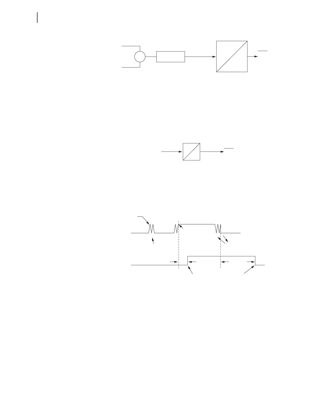
AC Mode Processing (AC Control Voltage)
Figure 4.110 shows IN101R from Input IN101 applied to a pickup/dropout
timer. Different from the dc mode, there are no time settings for the debounce
timer in the ac mode: the pickup time delay is fixed at 2 ms, and the dropout
time is fixed at 16 ms. Relay Word bit IN101 is the output of the debounce
timer. To select the ac mode of debounce, set IN101D := AC.
Figure 4.110 AC Mode Processing
Figure 4.111 shows a timing diagram for the ac mode of operation. On the ris-
ing edge of IN101R, the pickup timer starts timing (points marked 1 in
Figure 4.111). If IN101R deasserts (points marked 2 in Figure 4.111) before
expiration of the pickup time setting, Relay Word bit IN101 does not assert, and
remains at logical 0. If, however, IN101R remains asserted for a period longer
than the pickup timer setting, then Relay Word bit IN101 asserts to a logical 1.
Figure 4.111 Timing Diagram for Debounce Timer Operation When Operating
in AC Mode
Deassertion follows the same logic. On the falling edge of IN101R, the drop-
out timer starts timing. If IN101R remains deasserted for a period longer than the
dropout timer setting, then Relay Word bit IN101 deasserts to a logical 0.
Table 4.79 shows the settings prompt, setting range, and factory-default set-
tings for a card in Slot C. See the SEL-751 Settings Sheets for a complete list of
input debounce settings.
pu
do
IN101
Relay
Word
Bit
Input IN101
IN101R
Electrical
Isolator
Debounce Timer
2 ms
16 ms
IN101
Relay
Word
Bit
IN101R
Debounce Timer
IN101R
2 ms
IN101R Deasserted;
DDOT Counts
IN101R Deasserted;
DDOT Counts
Dropout Time
(16 ms)
Debounce Dropout
Timer Expires;
Relay Word Bit
IN101 Deasserts
Debounce Pickup
Timer Expires;
Relay Word Bit
IN101 Asserts
IN101R Asserted;
DPUT Counts
IN101R Asserted;
DPUT counts
Relay Word
Bit IN101
1
2
111 11
222 22
DPUT = Debounce Pickup Timer
DDOT = Debounce Dropout Timer
1 = Rising Edge: DPUT Counts
2 = Falling Edge: DDOT Counts