2.38
SEL-751 Relay Instruction Manual Date Code 20170927
Installation
AC/DC Control Connection Diagrams
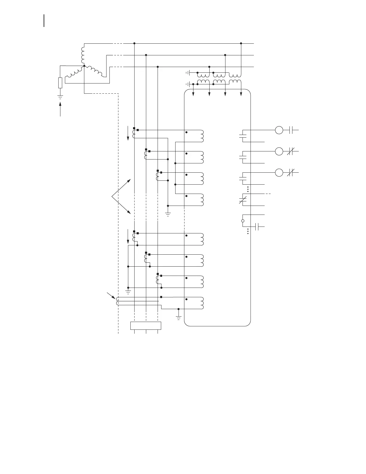
A core-balance current transformer is often referred to as a zero-sequence, ground fault, or window current transformer.
The lower CT wiring option (with the core-balance current transformer) is the preferred option (greater sensitivity; no
false residual currents due to CT saturation, etc.).
Directional control for a low-impedance grounded system is selected with setting ORDER containing S. Directional
control for a high-impedance grounded system is selected with setting ORDER := U (see Table 4.19–Table 4.21).
Nondirectional sensitive earth fault (SEF) protection is also available.
Figure 2.29 SEL-751 Provides Overcurrent Protection for a High-Impedance or Low-Impedance
Grounded System (Wye-Connected PTs)
TC
Trip
Coil
52A
(+)
(—)
Trip
Circuit
IA
C
B
A
SEL-751 RELAY
OUT103
Forward Tripping Direction
CC
Close
Coil
52B
(+)
(—)
Close
Circuit
IB OUT102
86
Lock
Out
86B
(+)
(—)
Breaker
Failure
Trip
Circuit
IC OUTxxx
OUT101
IN
FEEDER
52
(+)
52A
ALARM
(+)
(—)
Breaker Status
INxxx
IA
Forward Tripping Direction
IB
IC
IN
ANBC
CT Wiring Options
Pass neutral (N) through
core-balance CT only if neutral
is brought out and it is
grounded only at the source
Low-Impedance
or
High-Impedance
Grounded
+
+
to Annunciator, RTU,
or SEL Communications
Processor
VCNVBVA